FusionServer 2488H V5 Server
Technical White Paper
5 Hardware Description
Issue 07 (2023-04-30)
Copyright © xFusion Digital Technologies Co., Ltd.
53
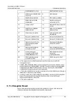
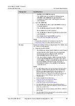
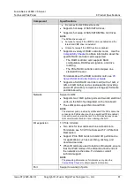
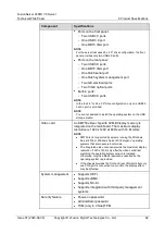
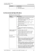
PORT0&PORT1/J140)
PORT2&PORT3/J138)
7
USB 3.0 port (REAR USB
3.0/J172)
8
UID Indicator
9
Health status indicator
10
RTC battery (U4042)
11
TPM/TCM port (TPM
CONN/J55)
12
Right mounting ear
connector (J131)
13
Jumper (J93)
b
14
SATA DVD drive connector
(J130)
15
USB 3.0 port (FRONT
USB3.0/J190)
c
16
USB 3.0 port (INNER
USB3.0/J182)
17
VGA connector (J233)
18
LCD connector (LCD
CONN/J87)
19
Fan port 4 (FAN4/J102)
20
Fan port 3 (FAN3/J103)
21
Fan port 2 (FAN2/J104)
22
Fan port 1 (FAN1/J105)
23
Signal connector for the
drive backplane (HDD
BP/J235)
24
High-speed backplane
connector (J244)
d
25
High-speed backplane
connector (J243)
d
26
Drive backplane power
connector (BP PWR/J237)
27
Left mounting ear
connector (LEFT EAR
CONN BOARD/J115)
28
PSU backplane power
connector
(J225/J226/J239)
29
PSU backplane signal
connector (J238)
30
VROC key port (J144)
e
⚫
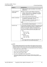
a: The upper one is an RJ45 serial port, and the lower one is an RJ45
management port.
⚫
b: BMC_SER_MANUAL PIN is used to change the connection direction of the
physical serial port. CLEAR_BMC_PW PIN is used to restore the default iBMC
configuration (for iBMC V350 and later versions, restoring the default iBMC
configuration through a jumper is not supported).
⚫
c: The built-in USB 3.0 port can be connected to the front USB 3.0 port through a
USB cable. It cannot be used directly.
⚫
d: CPUs 1 and 2 are on the mainboard, and CPUs 3 and 4 are on the daughter
board. The mainboard and daughter board are interconnected through
high-speed backplane connectors.
⚫
e: The port is reserved.
5.11.2 Daughter Board
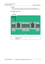
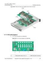
Figure 5-39 shows the daughter board of the 2488H V5. Figure 5-40 shows the
connection between the daughter board and the mainboard.

