


XFP USER MANUAL & LOG BOOK • Approved Document No. DFU2000501 Rev 2 • Page 15 of 28
XFP NETWORKABLE ANALOGUE ADDRESSABLE FIRE ALARM PANEL
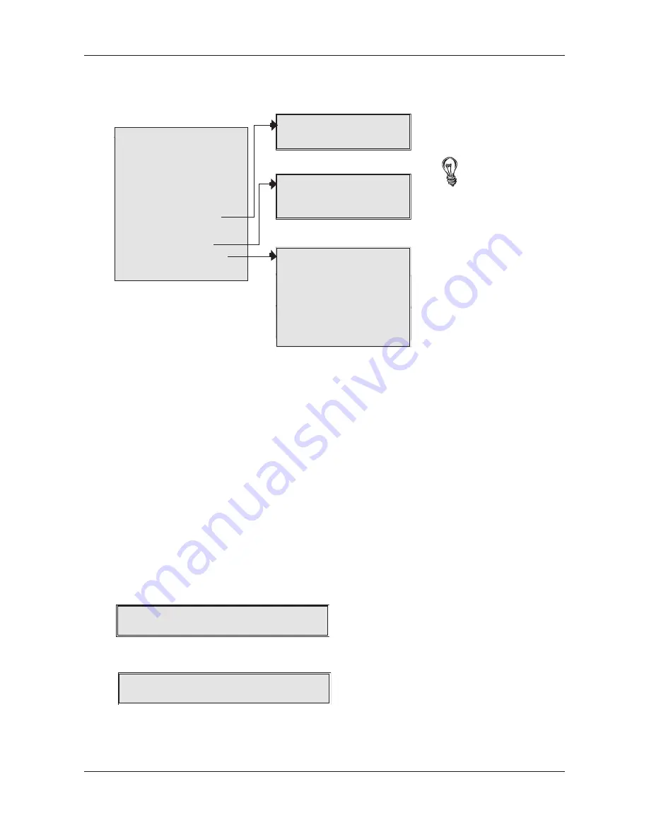
When in access level 2 (see page 14) the following menu options wil be available at the panel’s display
for authorised users. They can be navigated using the panel’s scroll (
56
), accept (
4
) and escape
(
3
) buttons as appropriate.
Enter Access Level 3
Access Level 3 is the panel’s engineering/programming level. ON NO ACCOUNT SHOULD ACCESS
LEVEL 3 BE ACCESSED BY ANYONE BUT AN AUTHORISED SYSTEM ENGINEER. A FIRE PANEL IS A PIECE
OF LIFE SAFETY EQUIPMENT AND UNAUTHORISED ACCESS MAY AFFECT THE WAY THE PANEL FUNC-
TIONS, ENDANGER LIFE AND VOID ITS WARRANTY. If you are an authorised engineer, details of
access level 3 can be found in the panel’s separate Engineering manual.
Lamp test
This function tests the panel’s lamps (its LED indicators and display) to ensure they are working correctly.
When selected, press the accept
4
button and all of the panel’s LED indicators will illuminate steady
for approximately two seconds and its display will progressively block fill. The panel’s internal sounder
(if enabled) will also sound. Upon completion, the panel will return to the main access level 2 menu.
If any of the LEDs fail to illuminate or the display does not function correctly, report the fault(s) to the
designated site engineer and make a note of it in the fire system’s log book.
Display alarm counter
This function displays the total number of times the panel has been in a fire alarm condition. When
selected, press the accept
4
button and the display will show the total number of times the panel
has been in a fire condition since it was installed AND the total number of times it has been in alarm
since its alarm counter was last cleared, for example:-
Press the escape
3
button to return to the main access level 2 menu or, to clear the alarm counter,
press the accept
4
button. A window similar to the one overleaf will appear:-
Press the accept
4
button once and the alarm counter will reset and start counting any new fire
conditions from today’s date (assuming that the date programmed into the panel is today’s date).
A short confirmation message will confirm the change has been made before the display returns to
the main access level 2 menu.
ENTER ACCESS LEVEL 3
DISPLAY FIRE EVENTS
DISPLAY FAULT EVENTS
DISPLAY DISABLEMENTS
DISPLAY ZONES IN TEST
LAMPS TEST
DISPLAY ALARM COUNTER
SET TIME/DATE
EVENT LOG FUNCTIONS
SET/CLEAR DISABLEMENTS
CHANGE ACCESS LEVEL 2 CODE
DISPLAY ALARM COUNTER
Clear to todays date?
PRINT EVENT HISTORY?
DISPLAY EVENT HISTORY?
RESET EVENT HISTORY?
ENABLE/DISABLE ZONES
ENABLE/DISABLE SOUNDERS
ENABLE/DISABLE OUTPUTS
ENABLE/DISABLE RELAYS
ENABLE/DISABLE DEVICES
ENABLE/DISABLE FAULT RELAY
ENABLE/DISABLE OUTPUT DELAYS
ENTER ACCESS LEVEL 2
ENTER ACCESS LEVEL 3
DISPLAY FIRE EVENTS
DISPLAY FAULT EVENTS
DISPLAY DISABLEMENTS
DISPLAY ZONES IN TES
T
LAMPS TEST
DISPLAY ALARM COUNTER
Total Alarms = 12
Alarms since 01/01/05 = 7
The menu options shown
in bold will only appear if
relevant to the panel’s
status. For example, the
DISPLAY FIRE EVENTS
function will not show if
there are no active fire
conditions on the system.
If any of these bold menus
appear, refer to their
listings in access level 1
(pages 12-13) for details of
how they work.
Clear to today's date?
Alarm since 01/01/05 = 7


