6
+12V
GND
STATUS
IR IN
9
8
6
7
4
5
2
3
1
EXP9
Zone IR Inputs section
120 V AC
(Unswitched)
782-00
Power Supply
Smart Pad
2
™
(Four shown)
780-80
"J" Box
IR Receivers
(Five shown)
V
S
ST
G
V
S
ST
G
V
S
ST
G
V
S
ST
G
V
S
ST
G
+12V
(white
striped
side)
GND
GND
+12V
V
S
ST
G
V
S
ST
G
V
S
ST
G
V
S
ST
G
V = +12V
S = Signal
ST = Status
G = GND
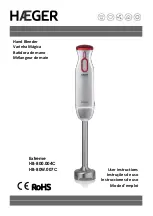
ZONE IR INPUTS
CB18
"The Strip-IR"
Connecting Block
Fig. 5
Using a CB18 to provide a +12V DC rail to externally power extra keypads and IR receivers to prevent overload
of the internal power supply of the EXP9.
[Remember, the Status lines (5 mA ea.) of these 11 Smart Pad
2
's remain connected to the STATUS
terminals on the EXP9 zones].
Fig. 5 illustrates how a CB18 "Strip-IR" Parallel Connecting Block can be used to provide a separate +12V
DC rail. This powers the additional keypads (and IR receivers, if needed) independent of the +12V of the
EXP9.
NOTE: The 782-00 Power Supply has a capacity of 1000 mA. If you have a system that is so extensive
that the total current exceeds the 1.8 A limit of the EXP9 by more than 1000 mA, use two 782-00's connected
so that two se12V DC rails are created. Connect two groups of the extra devices so that the total
excess load is shared equally between the two 782-00's.
CAUTION: To prevent current "hogging" and power supply shutdown, never connect a 782-00 in parallel
with the +12V terminal of the EXP9 or in parallel with another 782-00!
TROUBLESHOOTING
If you encounter problems with the setup or operation of the EXP9, review each of the following items and
take corrective action as described. If problems persist, contact Xantech Technical Support.
1. I have connected sources, zone amplifiers, IR receivers or keypads and the power supply. The
POWER LED comes on but the EXP9 does not respond to any IR commands from the RC68
Handheld Programmer.
a) The most frequent reason for this problem is that the RC68 Handheld Programmer is not set to the
correct IR Code Group. It must be set to 68 to work with the EXP9 (unless you have intentionally
changed the EXP9 to a different Code Group number).
EXP9