08905076A
-
2
-
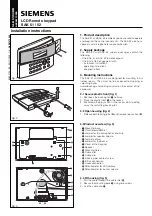
INSTALLATION
1. First, decide on the button labels you need and their locations.
2. Pick up the
Key Module PCB & Base
assembly and carefully place each button label onto the
Rubber Actuators
in the location you desire.
3. When the button labels are completely in place, place the
Clear Button Cap
over the
Button
Label
and
Rubber Actuators
.
NOTE: As received from the factory, the
Key Module Shell
is separate
from the
Key Module PCB & Base
Assembly.
4. Pick up the
Key Module Shell
and lower it over the
Key Module PCB & Base
assembly.
5. Move the buttons slightly, as necessary, to align them so that they pass through the button
openings in the
Key Module Shell
.
6. Carefully press the
Key Module Shell
down until the 4 small Retainer Tabs on the
Key
Module PCB & Base
assembly snap into the corresponding
Retainer Slots
in the
Key
Module Shell
.
7. Mount the completed Key Module into the PM or LM or EM. Place the front tab of the Key
Module under the small lip of the LM, PM or EM. Align the 18-pin connector with the 18-pin
socket and carefully push into place.