background image


4


 2 


Calibration and Measurement


FREQUENCY OF CALIBRATION 

Typically, the host computer prompts for an instrument calibration when required. The frequency at which this occurs 
depends on the application. If desired, a reflection calibration can be invoked manually by pressing the Instrument 
button—refer below for procedure. At a minimum the instrument should be calibrated once a day for best accuracy. 

REFLECTION MODE CALIBRATION 

The X-RiteColor AutoScan Spectrophotometer has a unique automatic calibration feature. When the instrument performs a 
calibration procedure, the Color Reflection Reference is automatically scanned, simplifying the procedure. The instrument 
employs a number of self-checking procedures to verify calibration accuracy during normal use. When internal limits are 
exceeded, the computer calls for a calibration.  

CALIBRATION NOTE:


Handle Color Reflection Reference by the edges. Make sure 
that the Color Reflection Reference is free of dust, dirt, and 
smudgemarks. Refer to Section Three for cleaning procedure. 
Always store the Color Reflection Reference in its protective 
envelope away from light and heat. 

1.


Center the designated end of the Color Reflection 
Reference under the alignment mark. Slowly insert strip 
past the front idler rollers up to the black bar on the 
reference strip. 

2.


To manually force the instrument into calibration mode, 
press and hold the Instrument button for a minimum of three 
seconds.

 The indicator light changes to yellow. Note, if calibration is 

not performed after a short period of time, the instrument returns to 
the measurement mode (green light). 

3.


Press the Instrument button again. The light slowly flashes yellow. 
After a few moments, the light changes to green and then back to 
slow flashing yellow. The strip is then pulled through the instrument 
and out the back. The light turns solid green after a successful 
calibration. If the calibration fails (fast flashing yellow light), verify 
strip is clean and re-read.  

4.


Place Color Reflection Reference in its protective envelope. 

NOTE:

 The optics block must remain in the T/W position when 

calibrating a DTP41/T instrument. 

TRANSMISSION MODE (BLACK) CALIBRATION 

NOTE: Transmission operation is optional. Therefore, transmission mode calibration may not be available on your 
instrument.  

A transmission calibration is recommended for the DTP41/T instrument approximately once a week for optimal 
performance. The host computer initiates the procedure and prompts you to insert the calibration envelope (transmission 
calibration cannot be initiated manually). This procedure guides you through the mechanical aspects of positioning the 
envelope in the instrument. 
 

1.


When the host computer indicates a transmission calibration is needed, center the designated end of the Color 
Reflection Reference Envelope under the alignment mark. Slowly insert past the front idler rollers until it comes to 
rest against the rear drive rollers (approx. three inches).


2.


Activate the cal procedure at the computer

. NOTE: This is a static measurement, the envelope is not  pulled through 

the instrument. 


The instrument beeps once, flashes yellow slowly and takes a series of five measurements. After completion, the 
instrument beeps again and the indicator light changes to solid green. 

3.


Remove the Color Reflection Reference Envelope from the Instrument. 

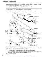
Press button 
down for 3 sec. to 
initiate calibration, 
then press button 
again 

Slowly insert strip up 
to the black bar 

Artisan Technology Group - Quality Instrumentation ... Guaranteed | (888) 88-SOURCE | www.artisantg.com

Summary of Contents for AutoScan DTP41 Series

Page 1: ...xcess underutilized and idle equipment along with credit for buybacks and trade ins Custom engineering so your equipment works exactly as you specify Critical and expedited services Leasing Rentals Demos In stock Ready to ship TAR certified secure asset solutions Expert team I Trust guarantee I 100 satisfaction All trademarks brand names and brands appearing herein are the property of their respec...

Page 2: ...AutoScan Spectrophotometer Instrument Operator s Manual Artisan Technology Group Quality Instrumentation Guaranteed 888 88 SOURCE www artisantg com ...

Page 3: ...Artisan Technology Group Quality Instrumentation Guaranteed 888 88 SOURCE www artisantg com ...

Page 4: ...erence causing equipment standard entitled Digital Apparatus ICES 003 of Industry Canada Avis de conformité aux normes d Indstrie Canada Cet appareil numérique respecte les limites de bruits radioélectriques applicables aux appareils numériques de Classe A prescrites dans la norme sur le matériel brouilleur Appareils numériques NMB 003 édictée par Industrie Canada NOTE Shielded interface cables mu...

Page 5: ...pection 1 Packaging Content 1 Instrument Interface 2 USB Driver Installation Windows Only 2 Instrument LED Indicator 3 Operation Mode Green Light 3 Calibration Mode Yellow Light 3 Error Reset Mode Red Light 3 Changing the Position of the Backing Block 3 2 Calibration and Measurement 4 Frequency of Calibration 4 Reflection Mode Calibration 4 Transmission Mode Black Calibration 4 Strip Positioning a...

Page 6: ...os brand names and product names are the properties of their respective holders Warranty Information X Rite Incorporated X Rite warrants each instrument manufactured to be free of defects in material and workmanship excluding battery pack for a period of 12 months This warranty shall be fulfilled by the repair or replacement at the option of X Rite of any part or parts free of charge including lab...

Page 7: ...Artisan Technology Group Quality Instrumentation Guaranteed 888 88 SOURCE www artisantg com ...

Page 8: ...the instrument from the shipping carton inspect it for damage If any damage has occurred during shipping immediately contact the transportation company Do not proceed with installation until the carrier s agent has inspected the damage Your instrument was packaged in a specially designed carton to assure against damage If shipment is necessary the instrument should be packaged in the original cart...

Page 9: ...t be installed in the computer to allow the instrument to work with your software application if the USB interface cable is used Follow the steps below to install the required USB driver 1 Make sure the switching power supply is plugged into the instrument and the computer in on 2 After the USB cable is plugged into your computer you must install the USB driver that came with your instrument 3 The...

Page 10: ...nges from Green or Yellow to Red While the LED is Red press button again within 10 seconds The LED changes to Green and the reset is performed reinstating the factory defaults If the second button press is not performed when the LED is Red the instrument will time out causing the LED to change to Green and the reset to be aborted CHANGING THE POSITION OF THE BACKING BLOCK NOTE Instruments that uti...

Page 11: ...llow After a few moments the light changes to green and then back to slow flashing yellow The strip is then pulled through the instrument and out the back The light turns solid green after a successful calibration If the calibration fails fast flashing yellow light verify strip is clean and re read 4 Place Color Reflection Reference in its protective envelope NOTE The optics block must remain in t...

Page 12: ... button the motor activates and automatically pulls the strip through the instrument For large strips media that extends outside the left side of the cover guide the strip with slight pressure This prevents skewing of the strip as it is measured Do not tug forwards or backwards on strip while internal motor is pulling strip through 1 Select strip type to measure from software 2 If required initiat...

Page 13: ...ment requires very little maintenance to achieve years of reliable operation However to protect your investment and maintain reading accuracy a few simple cleaning procedures should be performed from time to time General Cleaning Whenever required the exterior of the instrument may be wiped clean with a cloth dampened in water or mild cleaner NOTE DO NOT use any solvents to clean the unit this wil...

Page 14: ...naps into place When reassembling a transmission unit DTP41 T make sure the optics connector is properly seated before snapping into place CLEANING THE REFERENCE STRIP The calibration reference strip can be cleaned with a lint free cloth whenever required Make sure to return reference strip to its protective case when finished If required a new reference strip can be ordered from X Rite Part Numbe...

Page 15: ...es and what prompted them Have the hardware and software running within reach of the telephone INSTRUMENT SPECIFICATIONS Measurement Geometry 45 0 per ANSI ISO 5 4 IT2 17 Reflection 180 0 per ANSI ISO 5 2 IT2 19 Transmission Spot Size at Sample 1 8mm 070 in in scan direction 2 5mm 097 in wide Light Source Gas Pressure 2850 K Spectral Sensor DRS Technology 24 point engine 31 point reporting Spectra...

Page 16: ...Artisan Technology Group Quality Instrumentation Guaranteed 888 88 SOURCE www artisantg com ...

Page 17: ...rdstrasse 70 8105 Regensdorf Switzerland Phone 41 44 842 24 00 Fax 41 44 842 22 22 Corporate Headquarters Asia Room 808 810 Kornhill Metro Tower 1 Kornhill Road Quarry Bay Hong Kong Phone 852 2 568 6283 Fax 852 2 885 8610 Please visit www xrite com for a local office near you P N DTP41 500 Rev O Artisan Technology Group Quality Instrumentation Guaranteed 888 88 SOURCE www artisantg com ...

Page 18: ...quipment Have surplus equipment taking up shelf space We ll give it a new home Learn more Visit us at artisantg com for more info on price quotes drivers technical specifications manuals and documentation Artisan Scientific Corporation dba Artisan Technology Group is not an affiliate representative or authorized distributor for any manufacturer listed herein We re here to make your life easier How...

Reviews: