6
Technical support: [email protected] EMEA/ROW: +44 (0) 1793 230 343
US/CAN/MEX: +1-518-289-1294 Toll Free Technical Support: +1-844-280-WYRE (9973)
CONNECTION
1
2
!
!
!
3
4
5
6
7
8. Connection
Do not connect the Enado Controller to
the mains until you have made all the following
connections.
Connect a good quality, well-terminated Cat5e/6
cable with RJ45 connectors wired to the 568B standard
at both ends to the Enado Ethernet switch and the router
or primary network switch. Ensure the cable is tested
and measures less than 100m/328ft, with all connectors
pushed securely to ports and supported by connector
strain relief clips to prevent them from becoming loose.
The quality of cable and RJ45 termination is
essential for successful distribution transmissions.
Poor cable and terminations lead to intermittent
performance and longer install times.
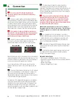
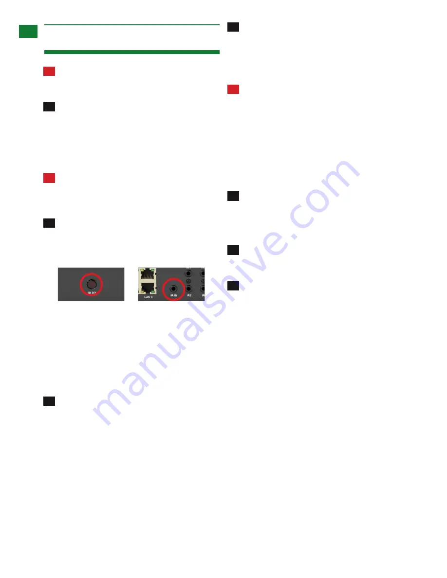
The IR TX receiver window on the front panel & the
IR TX port on the rear of the Enado Controller are
electronically linked and should not be used together.
Rear IR IN should only be connected if it is not possible to
receive IR signals via the front panel for learning, such as
if the IR TX window is obstructed or the unit is enclosed
so cannot receive an IR signal from a handset.
In such cases the rear IR TX receiver eye should be
placed in clear line of site to the control device used to
control.
The rear of the Enado controller has 16 x IR outputs
used to control displays or other devices in zones and
sources local to the controller, with the user able to
designate the balance of output devices or local sources
to be controlled through the system.
For example, if the application requires an even balance
of inputs and outputs for control within an 8x8 matrix
distribution, the user should connect 8 IR outputs from
the Enado Controller to the IR RX ports of the matrix
using the supplied mono IR Link cables to enable control
of output devices in display zones.
The remaining 8 Enado IR outputs should be
connected to sources local to the controller via the
supplied Y IR emitters, with one jack connecting to the IR
ports of the Enado Controller and the other connecting
to the corresponding source IR TX ports on the matrix to
enable IR pass-through.
IR eyes should be attached with the adhesive
backing directly over the infrared receiving area
of sources, ensuring there is a clear line-of-sight
with the remote control handset used to control.
Location of the IR eye may need to be adjusted later
to achieve best IR performance.
NOTE: Infrared windows can be seen by shining a
flashlight onto the front of the device – the IR sensor
will likely appear as a small round diode behind the
fascia.
For integration of a control system, connect an
RS232 cable between a matrix and the Enado Controller
– serial control for up to 4 matrices is supported, with
each matrix requiring individual RS232 connection to
ports 1-4 of the Enado Controller.
Connection of trigger GPIO (General Purpose input/
output) and sensor input system. See 6ii on Rear Panel
description.
Connect the power supply, making sure to ground
the chassis first to prevent electrical build up before
turning on the power supply.
Required Cable Types:
•
IR (to source): WyreStorm Enado ‘Y’ IR Emitter
•
IR (Enado to matrix): WyreStorm IR Link cable (CAB-IR-
LINK - 5v to 12v)
•
RS232: Null modem
•
Ethernet: Straight ‘patch’ lead
Front IR RX
Rear IR RX

