background image

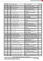
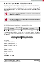
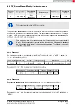
8.6. RF_DeviceName: Modify the device name

Settings

index

Designation

Permissible

values

Default value

Permissions

Number of

Bytes

2

RF_DeviceName

See

description

"Prot3"

read/write

1-31

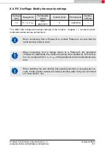
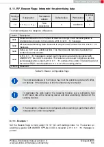
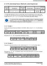
This parameter is using MSB first notation.

This parameter determines the name of the module, which is used in the advertising packets
as well as in the Generic Access Profile (GAP). The permissible characters are in the range
of 0x20 - 0x7E which are special characters (see ASCII table), alphabetic characters (a-z
and A-Z), numbers (0-9) and whitespace.

The maximum size of the device name that fits into an advertising packet is 5
Bytes. Thus longer device names will be shortened to 5 Bytes and declared
as "Shortened Local Name" in the advertising packet. The full device name is
included in the GAP.

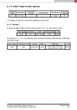
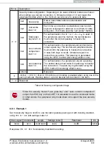
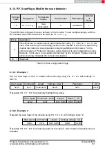
8.6.1. Example 1

Set the device name of the module to 0x4D 0x4F 0x44 0x20 0x31 = "MOD 1" using

CMD_

SET_REQ

with settings index 2.

Start signal

Command

Length

Settings index

Parameter

CS

0x02

0x11

0x06 0x00

0x02

0x4D 0x4F 0x44 0x20 0x31

0x40

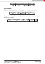
Response

CMD_SET_CNF

Successfully modified the setting.

Start signal

Command | 0x40

Length

Status

CS

0x02

0x51

0x01 0x00

0x00

0x52

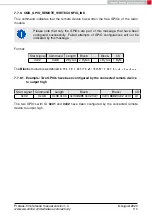
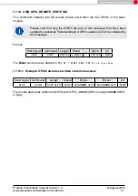
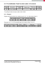
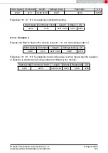
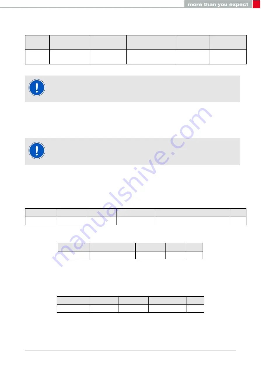
8.6.2. Example 2

Request the device name of the module using

CMD_GET_REQ

with settings index 2:

Start signal

Command

Length

Settings index

CS

0x02

0x10

0x01 0x00

0x02

0x11

Response

CMD_GET_CNF

Successfully read out the module as 0x41 0x32 0x37 0x32 0x31 =

"A2721".

Proteus-III reference manual version 1.3

© August 2020

www.we-online.com/wireless-connectivity

124

Summary of Contents for 2611011024000

Page 1: ...PROTEUS III REFERENCE MANUAL 2611011024000 VERSION 1 3 AUGUST 6 2020 ...

Page 2: ...tion and Example codes for host integration June 2020 1 2 1 1 0 1 2 corrected capacitor number C28 changed to C26 in section Trace design July 2020 1 3 1 1 0 1 2 Updated section Trace design Included figure On board PCB antenna and External antenna connection August 2020 For firmware history see chapter Firmware history Proteus III reference manual version 1 3 August 2020 www we online com wireles...

Page 3: ...M Low power mode Mode for efficient power consumption LRM Long range mode Radio mode with higher range and lower throughput MAC MAC address of the module MTU Maximum transmission unit Maximum packet size of the Bluetooth connection Payload The intended message in a frame package RF Radio frequency Describes wireless transmission RSSI Receive Signal Strength Indicator The RSSI indicates the strengt...

Page 4: ...D pins 33 5 2 Sleep mode 33 5 3 Identification of a Proteus III device on the radio 34 5 4 Connection based data transmission with or without security 34 5 4 1 Further information for a secure connection setup 35 5 4 1 1 Just works mode 35 5 4 1 2 StaticPasskey mode 38 5 4 1 3 LescPasskey mode 41 5 4 1 4 LescNumComp mode 45 5 4 1 5 Bonding 50 5 5 Unidirectional connectionless data transmission usi...

Page 5: ...NDS_REQ 73 7 2 13 1 Example 1 73 7 2 14 CMD_DELETEBONDS_REQ 74 7 2 14 1 Example 1 74 7 2 14 2 Example 2 75 7 3 Transmit and receive data 76 7 3 1 CMD_DATA_REQ 76 7 3 2 CMD_TXCOMPLETE_RSP 76 7 3 3 CMD_DATA_IND 77 7 3 4 CMD_SETBEACON_REQ 77 7 3 5 CMD_BEACON_IND 77 7 4 Configuring the module and modifying the device settings 79 7 4 1 CMD_SET_REQ 79 7 4 1 1 Example 1 80 7 4 1 2 Example 2 80 7 4 2 CMD_...

Page 6: ..._GPIO_REMOTE_READ_REQ 104 7 7 6 1 Example Read the values of remote GPIOs 105 7 7 7 CMD_GPIO_LOCAL_WRITE_REQ 106 7 7 7 1 Example Set a local output GPIO to low 107 7 7 8 CMD_GPIO_LOCAL_READ_REQ 108 7 7 8 1 Example Read the values of local GPIOs 109 7 7 9 CMD_GPIO_REMOTE_WRITECONFIG_IND 110 7 7 9 1 Example Two GPIOs have been configured by the connected remote device to output high 110 7 7 10 CMD_G...

Page 7: ...5 8 12 2 Example 2 135 8 13 RF_AdvertisingFlags Configure the advertising packet 136 8 13 1 Example 1 136 8 13 2 Example 2 136 8 14 RF_ScanFactor Modify the scan factor 138 8 14 1 Example 1 138 8 14 2 Example 2 138 8 15 RF_ScanTiming Modify the scan timing 139 8 15 1 Example 1 140 8 15 2 Example 2 140 8 16 RF_ConnectionTiming Modify the connection timing 141 8 16 1 Example 1 142 8 16 2 Example 2 1...

Page 8: ...t and sleep 163 9 2 Bluetooth LE timing parameters 163 9 3 Connection establishment 163 9 4 Connection based data transmission 164 9 4 1 Maximum data throughput 165 10 Peripheral only mode 166 10 1 Reasons to use the peripheral only mode 166 10 2 Restrictions 166 10 3 How to use the peripheral only mode 167 10 4 More information 167 10 4 1 Radio 167 10 4 2 UART 167 11 Remote GPIO control 170 11 1 ...

Page 9: ...gn 194 18 Manufacturing information 197 18 1 Moisture sensitivity level 197 18 2 Soldering 197 18 2 1 Reflow soldering 197 18 2 2 Cleaning 199 18 2 3 Other notations 199 18 3 ESD handling 199 18 4 Safety recommendations 200 19 Physical dimensions 201 19 1 Dimensions 201 19 2 Weight 201 19 3 Module drawing 202 19 4 Footprint 203 19 5 Antenna free area 203 20 Marking 204 20 1 Lot number 204 20 2 Gen...

Page 10: ...mprovements 216 24 6 Product life cycle 216 24 7 Property rights 216 24 8 General terms and conditions 216 25 Legal notice 217 25 1 Exclusion of liability 217 25 2 Suitability in customer applications 217 25 3 Trademarks 217 25 4 Usage restriction 217 26 License terms 219 26 1 Limited license 219 26 2 Usage and obligations 219 26 3 Ownership 220 26 4 Firmware update s 220 26 5 Disclaimer of warran...

Page 11: ...fications of such applications a tailored firmware can be developed on the basis of the Proteus III hardware This includes the connection and communication to custom sensors custom Bluetooth LE profiles timing configurations security configuration as well as power consumption optimizations Even with it s small dimensions of 8 x 12 mm the Proteus III provides a strongly miniaturized integrated PCB ...

Page 12: ...ocessor generation provided by Nordic Semiconductor nRF52 series The heart of the Proteus III is a Bluetooth LE chip of the nRF52 series offering high performance values combined with low power consumption It is a 32 Bit ARM Cortex M4F CPU with 1024kB flash 256kB RAM and up to 8dBm output power Bluetooth 5 stack The Bluetooth 5 stack enables fast and energy efficient data trans mission using state...

Page 13: ...ows in addition to setup the connection immediately using the long range mode such that even connections can be initiated on high distances More information can be found in chapter 5 10 Fast sensor data transmission via Beacons The Proteus III supports the transmission and reception of Beacons Beacons are fast broadcast messages that allow the energy efficient unidirectional transmission of data E...

Page 14: ...nna Figure 2 Block diagram of the module 1 3 Ordering information WE order code Description 2611011024000 Proteus III Bluetooth LE Module Tape Reel 2611011024009 Development Kit including 3 Proteus III 2611019024001 Bluetooth LE Evaluation Kit with Proteus III EV board 2611036024001 USB Dongle Proteus III Plug integrated antenna Table 1 Ordering information Proteus III reference manual version 1 3...

Page 15: ... function properly for rise times longer than the specified maximum An instable supply voltage may significantly decrease the radio performance and stability 2 2 Absolute maximum ratings Description Min Typ Max Unit Supply voltage VDD 0 3 3 9 V Voltage on any digital pin VDD 3 6V 0 3 VDD 0 3 V Voltage on any digital pin VDD 3 6V 0 3 3 9 V Input RF level 10 dBm Flash endurance 10 000 Write erase cy...

Page 16: ...off mode 0 4 µA Reduction through CMD_UARTDISABLE_REQ 550 µA Table 4 Power consumption for 100 transmission reception Due to the Bluetooth LE time slot operation the real operating currents are reduced significantly and depend on the user selectable advertising and con nection interval settings 1 Transmitter only with DC DC converter from nRF52 data sheet CPU current not included 2 Full module pow...

Page 17: ... device in advertising mode see Figure 4 Currents and state durations are dependent on the configuration of the module In this state the module transmits the advertising packets on the three advertising channels Nordic Semiconductor provides an online tool calculating the average current of a Bluetooth connection It can be accessed at https devzone nordicsemi com power Proteus III reference manual...

Page 18: ...nt consumption calculation in advertising mode with 40ms advertising interval with 8 dBm output power UART SPI disabled Proteus III reference manual version 1 3 August 2020 www we online com wireless connectivity 17 ...

Page 19: ...vels are measured on the evaluation board The values already include losses of transitions from module to motherboard to SMA or modules PCB antenna They are realistic values for the end application Sensitivity in the table above is stated for the common used bit error rate of 0 1 In the table below the sensitivity is stated for a packet error rate of 1 with a payload length of 38 byte at different...

Page 20: ...V 6 10 15 mA Current at VSS 0 4 V output set low high drive VDD 1 7 V 3 mA Current at VDD 0 4 V output set high standard drive VCC 1 7V 1 2 4 mA Current at VDD 0 4 V output set high high drive VDD 2 7 V 6 9 14 mA Current at VDD 0 4 V output set high high drive VDD 1 7 V 3 mA Internal pull up resistance 11 13 16 kΩ Internal pull down resistance 11 13 16 kΩ Table 8 Pin characteristics Proteus III re...

Page 21: ...in functionality is accessible through pad 1 18 with edge castellation This offers easy prototype building as it is suitable for hand soldering More optional GPIOs without enlarging the size are accessible through the land grid pads B1 B6 that can only be connected through reflow process Proteus III reference manual version 1 3 August 2020 www we online com wireless connectivity 20 ...

Page 22: ...al Mode High level Peripheral only Mode Do not connect if not needed 10 P0 22 BUSY Output Indicates if module is busy with data transmis sion when using Peripheral only Mode see sec tion 10 4 2 Do not connect if not needed 11 P0 00 XL12 LED_1 Output Indicates the module state active high Do not connect if not needed 12 P0 01 XL22 LED_2 Output Indicates the module state active high Do not connect i...

Page 23: ... P0 10 NFC23 B2 GPIO Pin for remote GPIO access Do not connect if not needed B3 P0 23 B3 GPIO Pin for remote GPIO access Do not connect if not needed B4 P1 00 B4 GPIO Pin for remote GPIO access Do not connect if not needed B5 P0 21 B5 GPIO Pin for remote GPIO access Do not connect if not needed B6 P0 07 B6 GPIO Pin for remote GPIO access Do not connect if not needed Table 10 Pinout second part 3 N...

Page 24: ... Connect the UART pins UTXD and URXD to the host to control the module via host 3 UART flow control In case of fast UART baudrates higher than 115 2 kbaud the UART flow control is activated automatically For lower data rates the flow control is inactive per default If activated the RTS and CTS pins must be connected to the host controller 4 Antenna connection The antenna configuration must be perf...

Page 25: ...ommended to additionally have the pins SWDIO and SWDCLK accessible in order to support a fail safe firmware update A standard socket on the customer s PCB for connecting a flash adapter can be useful for debugging purposes e g a JTAG 2 10 pin header with 2 54mm pin to pin distance If the module has to be connected to a PC a converter TTL to RS 232 or TTL to USB has to be used See chapter 3 for det...

Page 26: ... antenna For applications that use an external antenna the Proteus III provides a 50Ω RF signal on pin RF of the module In this configuration pin ANT of the module has to be connected to ground and pin RF to the external antenna via 50Ω feed line Refer to chapter 17 for further information The use cases for the integrated antenna are miniaturization and re use of module certifications for the end ...

Page 27: ...end a CMD_GETSTATE_CNF to indicate ready for operation after the RESET pin was released Applying a reset e g a host temporarily pulling the RESET pin down for at least 1ms and releasing it again after the VCC is stable will also be sufficient Figure 7 Power up Proteus III reference manual version 1 3 August 2020 www we online com wireless connectivity 26 ...

Page 28: ...r of Proteus III EV is recommended Connect the two devices modules EV boards or USB dongles to a PC A terminal pro gram for example hterm is used to perform the communication via COM ports The two corresponding COM ports have to be selected and opened with a default configuration of 115200 Baud 8 data Bits 1 stop Bit and parity set to none 8n1 To reproduce the following sequence note that the MAC ...

Page 29: ...TION_IDLE mode 02 41 02 00 01 01 41 2 Request the FS_BTMAC of both modules Info Module A Module B Request CMD_GET_REQ with settings index 4 02 10 01 00 04 17 Response CMD_GET_CNF FS_BTMAC of module A is 0x55 0x00 0x00 0xDA 0x18 0x00 02 50 07 00 00 55 00 00 DA 18 00 C2 Request CMD_GET_REQ with settings index 4 02 10 01 00 04 17 Response CMD_GET_CNF FS_BTMAC of module B is 0x11 0x00 0x00 0xDA 0x18 0...

Page 30: ... 00 F3 E3 Indication CMD_CHANNELOPEN_RSP Channel opened successfully to module with FS_BTMAC 0x55 0x00 0x00 0xDA 0x18 0x00 and maximum payload size of 0xF3 243 Bytes per packet 02 C6 08 00 00 55 00 00 DA 18 00 F3 A7 4 Once the connection is active data can be sent in each direction Let us send a string ABCD from module B to module A The RSSI values will be different in your tests Info Module A Mod...

Page 31: ...LETE_RSP Data transmitted successfully 02 C4 01 00 00 C7 6 Now module A closes the Bluetooth LE connection so both modules will get a dis connect indication message Info Module A Module B Request CMD_DISCONNECT_REQ Disconnect 02 07 00 00 05 Response CMD_DISCONNECT_CNF Request received disconnect now 02 47 01 00 00 44 Indication CMD_DISCONNECT_IND Connection closed 02 87 01 00 16 92 Indication CMD_...

Page 32: ...r devices in range can detect it and connect to it The ACTION_IDLE state also allows to switch to ACTION_SCANNING state where the module stops advertising and scans for other advertising Bluetooth LE devices in range When leaving the ACTION_SCANNING state with the corresponding command the module is in ACTION_IDLE state and starts advertising again The ACTION_CONNECTED state can be entered either ...

Page 33: ...NUMERIC_COMP CMD_GPIO_LOCAL_CONFIG_REQ CMD_GPIO_REMOTE_WRITE_REQ CMD_GPIO_REMOTE_READ_REQ CMD_GPIO_LOCAL_WRITE_REQ CMD_GPIO_LOCAL_READ_REQ ACTION_SLEEP The module is in sleep mode and waits for a wakeup event Permitted commands None ACTION_DTM The module is in direct test mode Permitted commands CMD_DTM_REQ CMD_RESET_REQ CMD_GETSTATE_REQ ACTION_CONNECTED The module is connected Now data can be tra...

Page 34: ...hen enter the ACTION_SLEEP mode In ACTION_SLEEP mode the UART is disabled Thus the module will not receive or transmit any data To prevent leakage current the host shall not pull the URXD to LOW level as the module has an internal pull up resistor enabled on this pin To leave the ACTION_SLEEP mode and enter ACTION_IDLE state again the module has to be woken up by applying a low signal to the WAKE_...

Page 35: ...sed to setup a connection with module B the host of module A must send the command CMD_CONNECT_REQ including the FS_BTMAC of module B to module A If the FS_BTMAC of module B is unknown a radio scan shall be run before by module A to discover all available Bluetooth LE enabled devices in range After sending the command CMD_CONNECT_REQ the module answers with a CMD_CONNECT_CNF to signal that the req...

Page 36: ...ty level is not met by the central device no access to the peripheral s profiles will be granted When connecting from a Proteus III to a Proteus III you shall not use different security modes To get further information about the secured connection setup when using a foreign device i e mobile phone with a custom APP please refer to the Proteus III application note ANR009 advanced developer guide 5 ...

Page 37: ...xDA 0x18 0x00 02 50 07 00 00 11 00 00 DA 18 00 86 3 Configure the parameter RF_SecFlags to use Just Works pairing method for Bluetooth security Info Module A Module B Perform CMD_SET_REQ with settings index 12 and value 0x02 on module A 02 11 02 00 0C 02 1F Response CMD_SET_CNF Module will restart to adopt the new value 02 51 01 00 00 52 Response CMD_GETSTATE_CNF 02 41 02 00 01 01 41 Perform CMD_S...

Page 38: ... 00 00 DA 18 00 5C Indication CMD_SECURITY_IND status 0x02 encrypted link pairing no bonding with FS_BTMAC 0x55 0x00 0x00 0xDA 0x18 0x00 02 88 07 00 02 55 00 00 DA 18 00 18 Indication CMD_CHANNELOPEN_RSP Channel opened successfully to module with FS_BTMAC 0x11 0x00 0x00 0xDA 0x18 0x00 and maximum payload size of 0xF3 243 Bytes per packet 02 C6 08 00 00 11 00 00 DA 18 00 F3 EC Indication CMD_CHANNE...

Page 39: ...0 C1 45 46 47 48 D7 Response CMD_TXCOMPLETE_RSP Data transmitted successfully 02 C4 01 00 00 C7 7 Now module A closes the connection so both modules will get a disconnect indication Info Module A Module B Request CMD_DISCONNECT_REQ Disconnect 02 07 00 00 05 Response CMD_DISCONNECT_CNF Request received disconnect now 02 47 01 00 00 44 Indication CMD_DISCONNECT_IND Connection closed 02 87 01 00 16 9...

Page 40: ..._GET_REQ with settings index 4 02 10 01 00 04 17 Response CMD_GET_CNF FS_BTMAC of module A is 0x55 0x00 0x00 0xDA 0x18 0x00 02 50 07 00 00 55 00 00 DA 18 00 C2 Request CMD_GET_REQ with settings index 4 02 10 01 00 04 17 Response CMD_GET_CNF FS_BTMAC of module B is 0x11 0x00 0x00 0xDA 0x18 0x00 02 50 07 00 00 11 00 00 DA 18 00 86 3 Configure the parameter RF_SecFlags to use StaticPasskey pairing me...

Page 41: ...RITY_IND status 0x02 encrypted link pairing no bonding with FS_BTMAC 0x11 0x00 0x00 0xDA 0x18 0x00 02 88 07 00 02 11 00 00 DA 18 00 5C Indication CMD_SECURITY_IND status 0x02 encrypted link pairing no bonding with FS_BTMAC 0x55 0x00 0x00 0xDA 0x18 0x00 02 88 07 00 02 55 00 00 DA 18 00 18 Indication CMD_CHANNELOPEN_RSP Channel opened successfully to module with FS_BTMAC 0x11 0x00 0x00 0xDA 0x18 0x0...

Page 42: ...A 18 00 C1 45 46 47 48 D7 Response CMD_TXCOMPLETE_RSP Data transmitted successfully 02 C4 01 00 00 C7 7 Now module A closes the connection so both modules will get a disconnect indication Info Module A Module B Request CMD_DISCONNECT_REQ Disconnect 02 07 00 00 05 Response CMD_DISCONNECT_CNF Request received disconnect now 02 47 01 00 00 44 Indication CMD_DISCONNECT_IND Connection closed 02 87 01 0...

Page 43: ...power up or after reset the following sequence is sent from the module to the host Info Module A Module B Response CMD_GETSTATE_CNF Module A started in ACTION_IDLE mode 02 41 02 00 01 01 41 Response CMD_GETSTATE_CNF Module B started in ACTION_IDLE mode 02 41 02 00 01 01 41 2 Request the FS_BTMAC of both modules Info Module A Module B Request CMD_GET_REQ with settings index 4 02 10 01 00 04 17 Resp...

Page 44: ...nse CMD_GETSTATE_CNF 02 41 02 00 01 01 41 Perform CMD_SET_REQ with settings index 12 and value 0x05 on module B 02 11 02 00 0C 05 18 Response CMD_SET_CNF Module will restart to adopt the new value 02 51 01 00 00 52 Response CMD_GETSTATE_CNF 02 41 02 00 01 01 41 4 Connect module A to module B via Bluetooth Proteus III reference manual version 1 3 August 2020 www we online com wireless connectivity ...

Page 45: ...e CMD_PASSKEY_CNF Pass key ok 02 4D 01 00 00 4E Indication CMD_SECURITY_IND status 0x02 encrypted link pairing no bonding with FS_BTMAC 0x11 0x00 0x00 0xDA 0x18 0x00 02 88 07 00 02 11 00 00 DA 18 00 5C Indication CMD_SECURITY_IND status 0x02 encrypted link pairing no bonding with FS_BTMAC 0x55 0x00 0x00 0xDA 0x18 0x00 02 88 07 00 02 55 00 00 DA 18 00 18 Indication CMD_CHANNELOPEN_RSP Channel opene...

Page 46: ... DA 18 00 C1 45 46 47 48 D7 Response CMD_TXCOMPLETE_RSP Data transmitted successfully 02 C4 01 00 00 C7 7 Now module A closes the connection so both modules will get a disconnect indication Info Module A Module B Request CMD_DISCONNECT_REQ Disconnect 02 07 00 00 05 Response CMD_DISCONNECT_CNF Request received disconnect now 02 47 01 00 00 44 Indication CMD_DISCONNECT_IND Connection closed 02 87 01...

Page 47: ...lowing sequence is sent from the module to the host Info Module A Module B Response CMD_GETSTATE_CNF Module A started in ACTION_IDLE mode 02 41 02 00 01 01 41 Response CMD_GETSTATE_CNF Module B started in ACTION_IDLE mode 02 41 02 00 01 01 41 2 Request the FS_BTMAC of both modules Info Module A Module B Request CMD_GET_REQ with settings index 4 02 10 01 00 04 17 Response CMD_GET_CNF FS_BTMAC of mo...

Page 48: ...nse CMD_GETSTATE_CNF 02 41 02 00 01 01 41 Perform CMD_SET_REQ with settings index 12 and value 0x04 on module B 02 11 02 00 0C 04 19 Response CMD_SET_CNF Module will restart to adopt the new value 02 51 01 00 00 52 Response CMD_GETSTATE_CNF 02 41 02 00 01 01 41 4 Connect module A to module B via Bluetooth Proteus III reference manual version 1 3 August 2020 www we online com wireless connectivity ...

Page 49: ...cess 02 64 01 00 00 67 Answer with the CMD_NUMERIC_COMP_REQ to confirm that both keys are equal 02 24 01 00 00 27 Response CMD_NUMERIC_COMP_CNF Request understood going on with the connection setup process 02 64 01 00 00 67 Indication CMD_SECURITY_IND status 0x02 encrypted link pairing no bonding with FS_BTMAC 0x11 0x00 0x00 0xDA 0x18 0x00 02 88 07 00 02 11 00 00 DA 18 00 5C Indication CMD_SECURIT...

Page 50: ...send data now 02 44 01 00 00 47 Indication CMD_DATA_IND Received string EFGH from FS_BTMAC 0x55 0x00 0x00 0xDA 0x18 0x00 with RSSI of 0xC1 63dBm 02 84 0B 00 55 00 00 DA 18 00 C1 45 46 47 48 D7 Response CMD_TXCOMPLETE_RSP Data transmitted successfully 02 C4 01 00 00 C7 7 Now module A closes the connection so both modules will get a disconnect indication Info Module A Module B Request CMD_DISCONNECT...

Page 51: ...llowing sequence is sent from the module to the host Info Module A Module B Response CMD_GETSTATE_CNF Module A started in ACTION_IDLE mode 02 41 02 00 01 01 41 Response CMD_GETSTATE_CNF Module B started in ACTION_IDLE mode 02 41 02 00 01 01 41 2 Request the FS_BTMAC of both modules Info Module A Module B Request CMD_GET_REQ with settings index 4 02 10 01 00 04 17 Response CMD_GET_CNF FS_BTMAC of m...

Page 52: ...o module with FS_BTMAC 0x11 0x00 0x00 0xDA 0x18 0x00 02 86 07 00 00 11 00 00 DA 18 00 50 Indication CMD_CONNECT_IND Physical connection established successfully to module with FS_BTMAC 0x55 0x00 0x00 0xDA 0x18 0x00 02 86 07 00 00 55 00 00 DA 18 00 14 Indication CMD_SECURITY_IND status 0x01 encrypted link bonding established with FS_BTMAC 0x11 0x00 0x00 0xDA 0x18 0x00 02 88 07 00 01 11 00 00 DA 18 ...

Page 53: ...ication CMD_CONNECT_IND Physical connection established successfully to module with FS_BTMAC 0x55 0x00 0x00 0xDA 0x18 0x00 02 86 07 00 00 55 00 00 DA 18 00 14 Indication CMD_SECURITY_IND status 0x00 encrypted link to bonded device with FS_BTMAC 0x11 0x00 0x00 0xDA 0x18 0x00 02 88 07 00 00 11 00 00 DA 18 00 5E Indication CMD_SECURITY_IND status 0x00 encrypted link to bonded device with FS_BTMAC 0x5...

Page 54: ...ng beacon data is received Filtering the beacon messages can be enabled or disabled using the user setting RF_BeaconFlags After the reception of the beacon data it is output to the connected host using a CMD_BEACON_ IND message To set the module into ACTION_SCANNING mode the command CMD_SCANSTART_REQ has to be used Enable the Beacon function before by setting the corresponding value in the RF_Beac...

Page 55: ... 00 00 00 02 Response CMD_RESET_CNF 02 40 01 00 00 43 Response CMD_GETSTATE_CNF 02 41 02 00 01 01 41 5 6 Energy efficient distance estimation solutions The transmitted advertising packet contains its TX power value This value in combination with the RSSI value of the received advertising packet can be used to estimate the distance between the modules Using a suitable triangulation algorithm and mu...

Page 56: ...avior of the module when advertising or scanning The less often the module sends advertising packets or scans the less current is consumed RF_ConnectionTiming This setting defines the timing behavior of the module during connection setup and during an open connection The less often the connected mod ules communicate with each other the less current is consumed The on board nRF52 SoC is running in ...

Page 57: ...n in hexadecimal notation All steps are described in the following First restart the modules in DTM mode Info Module A Module B Request CMD_DTMSTART_REQ to enable the DTM on module A 02 1D 00 00 1F Response CMD_DTMSTART_CNF Request understood try to start DTM now 02 5D 01 00 00 5E Indication CMD_GETSTATE_CNF Restarted module with DTM enabled 02 41 02 00 10 05 54 Request CMD_DTMSTART_REQ to enable ...

Page 58: ...nted with Bluetooth 5 0 It uses the Direct Sequence Spread Spectrum DSSS technique that spreads the signal and thus generates redundant informations On the receiver side it uses the Forward Error Correction FEC technique to use the redundancy to correct a received perturbed signal The combination of both the DSSS and FEC enable higher ranges in data transmission To be backward compatible to Blueto...

Page 59: ...scanning in legacy 1 Mbit mode by default Example Configure the device for long range connection setup The goal of this example is to demonstrate how to configure two Proteus III radio module to be able to setup connections in long range mode Further a connection setup and data transmission is shown 1 Power up the modules and make their UARTs accessible by the host s 115200 Baud 8n1 After the powe...

Page 60: ...T_IND Physical connection established successfully to module with FS_BTMAC 0x11 0x00 0x00 0xDA 0x18 0x00 02 86 07 00 00 11 00 00 DA 18 00 50 Indication CMD_CONNECT_IND Physical connection established successfully to module with FS_BTMAC 0x55 0x00 0x00 0xDA 0x18 0x00 02 86 07 00 00 55 00 00 DA 18 00 14 Indication CMD_CHANNELOPEN_RSP Channel opened successfully to module with FS_BTMAC 0x11 0x00 0x00...

Page 61: ...0 00 47 Indication CMD_DATA_IND Received string EFGH from FS_BTMAC 0x55 0x00 0x00 0xDA 0x18 0x00 with RSSI of 0xC1 63dBm 02 84 0B 00 55 00 00 DA 18 00 C1 45 46 47 48 D7 Response CMD_TXCOMPLETE_RSP Data transmitted successfully 02 C4 01 00 00 C7 7 Now module A closes the connection so both modules will get a disconnect indication Info Module A Module B Request CMD_DISCONNECT_REQ Disconnect 02 07 00...

Page 62: ... individual successive Bytes The host must not implement too strict timeouts between two Bytes to be able to receive packets that have interruptions in between 6 1 1 Reset behaviour When holding the module s RESET pin LOW the radio chip states are undefined In this case the modules UTXD pin may be pulled LOW by the radio module such that the con nected host controller s UART may detect a 0x00 byte...

Page 63: ... has been established Start signal Command Length Payload CS 0x02 1 Byte 2 Byte LSB first Length Bytes 1 Byte Start signal 0x02 1 Byte Command One of the predefined commands 1 Byte Length Specifies the length of the payload that follows Length is a 16 Bit field with LSB first Payload Variable number of data or parameters defined by the length field Checksum Byte wise XOR combination of all precedi...

Page 64: ...in specific module s tates see Figure 8 If a command is not permitted in the current state the command confirmation returns Operation not permitted as a response Proteus III reference manual version 1 3 August 2020 www we online com wireless connectivity 63 ...

Page 65: ...us CS 0x02 0x49 0x01 0x00 1 Byte 1 Byte Status 0x00 Request received will start scan now 0x01 Operation failed 0xFF Operation not permitted 7 1 2 CMD_SCANSTOP_REQ This command stops the scan operation that was started using CMD_SCANSTART_REQ It stores the detected Proteus III FS_BTMAC addresses in an internal database which can be output using the CMD_GETDEVICES_REQ Format Start signal Command Len...

Page 66: ...ata of the detected Devices devices It consists of Devices times the following telegram see example below BTMAC RSSI TXPower Device name length Device name 6 Bytes 1 Byte 1 Byte 1 Byte Device name length Bytes Status 0x00 Request received 0x01 Operation failed 0xFF Operation not permitted If there are too many devices found to be output the response of the CMD_ GETDEVICES_REQ is split into several...

Page 67: ... of 0x04 4 dBm and device name of length 5 with the value of 0x4D4F442031 MOD 1 Device 2 with FS_BTMAC 0x55 0x00 0x00 0xDA 0x18 0x00 and RSSI value of 0xE5 27 dBm TXPower of 0x00 0 dBm and device name 0x4D4F442032 MOD 2 of length 5 7 1 4 CMD_RSSI_IND This telegram indicates the reception of an advertising packet sent by another Proteus III module It can be used to realize a position sensing applic...

Page 68: ...n the RF_BeaconFlags is set If active scanning is enabled by setting the RF_ScanFlags received scan response packets are output in addition Besides the FS_BTMAC the RSSI value of the advertising packet and the raw data is output The accuracy is 2dB when inside the RSSI range of 90 to 20 dBm The format of the raw advertising data is described in the Bluetooth specifi cation version 5 1 Vol 3 Part C...

Page 69: ...es 1 Byte Response CMD_CONNECT_CNF Start signal Command 0x40 Length Status CS 0x02 0x46 0x01 0x00 1 Byte 1 Byte Status 0x00 Request received try to connect to the device with the FS_BTMAC 0x01 Operation failed 0xFF Operation not permitted 7 2 2 CMD_CONNECT_IND This telegram indicates the connection status and the FS_BTMAC of the connected device This indication message is the result of a connectio...

Page 70: ...tion request CMD_CONNECT_REQ Format Start signal Command Length Status BTMAC Max payload CS 0x02 0xC6 0x08 0x00 1 Byte 6 Bytes 1 Byte 1 Byte Status 0x00 Success 7 2 5 CMD_DISCONNECT_REQ This command shuts down the existing connection Thereafter the module prints a CMD_DISCONNECT_CNF to confirm that the request has been received the indication mes sage CMD_DISCONNECT_IND follows which determines wh...

Page 71: ...failed 7 2 7 CMD_PHYUPDATE_REQ This command allows to update the PHY of the current Bluetooth LE connection After the module prints a CMD_PHYUPDATE_CNF it tries to update the PHY The result is indicated by CMD_PHYUPDATE_IND message Format Start signal Command Length PHY CS 0x02 0x1A 0x01 0x00 1 Byte 1 Byte PHY 0x01 1 MBit PHY 0x02 2 MBit PHY 0x04 LE Coded mode 1 MBit PHY with DSSS and FEC for high...

Page 72: ...2 0x00 0x01 1 Byte 1 Byte Info 0x1A Unsupported feature of remote device 7 2 9 CMD_PASSKEY_REQ When receiving a CMD_PASSKEY_IND during connection setup the peripheral requests for a pass key to authenticate the connecting device To answer this request the CMD_PASSKEY_REQ message has to be sent to the Proteus III central including the passkey of the peripheral The permissible characters of the pass...

Page 73: ...entral side for authentication In case of the LescNumComp mode the central and peripheral output the passkey to their host Both hosts must reply with a CMD_NUMERIC_COMP_REQ message to confirm that both keys coincide Format Start signal Command Length Action BTMAC Pass key CS 0x02 0xA4 0x0D 0x00 1 Byte 6 Bytes 6 Bytes 1 Byte Action 0x00 Key is displayed to enter it on the central device no action n...

Page 74: ...S 0x02 0x0F 0x00 0x00 0x0D Response CMD_GETBONDS_CNF Start signal Command 0x40 Length Status Devices Payload CS 0x02 0x4F 2 Bytes 1 Byte 1 Byte Length 2 Bytes 1 Byte The Payload sequentially lists the data of the bonded Devices devices It consists of Devices times the following telegram see example below Bond_ID BTMAC 2 Bytes 6 Bytes Status 0x00 Request successfully processed 0x01 Operation failed...

Page 75: ... all or single bonded devices Enter Bond_ID to remove the bonding data of a certain Bond_ID To remove all bonding data choose Length equals 0 and leave Bond_ID empty Format Start signal Command Length Bond_ID CS 0x02 0x0E 2 Bytes 0 or 2 Bytes 1 Byte Response CMD_DELETEBONDS_CNF Start signal Command 0x40 Length Status CS 0x02 0x4E 0x01 0x00 1 Byte 1 Byte Status 0x00 Request successfully processed 0...

Page 76: ...ove the bonding of the device corresponding to Bond_ID 0 Start signal Command Length Bond_ID CS 0x02 0x0E 0x02 0x00 0x00 0x00 0x0E Response Start signal Command 0x40 Length Status CS 0x02 0x4E 0x01 0x00 0x00 0x4D Successfully removed the bonding information Proteus III reference manual version 1 3 August 2020 www we online com wireless connectivity 75 ...

Page 77: ...tted pay load data In high throughput mode the length of data packets may be up to 964 Bytes Format Start signal Command Length Payload CS 0x02 0x04 2 Bytes Length Bytes 1 Byte Response CMD_DATA_CNF Start signal Command 0x40 Length Status CS 0x02 0x44 2 Bytes Length Bytes 1 Byte Status 0x00 Request received will send data now 0x01 0xXX Operation failed 0xXX maximum payload size if it was exceeded ...

Page 78: ...ation message containing the trans mitted data See chapter 5 5 for more information Choosing 0x00 as Length and leaving the Payload field empty will remove the data from the scan response packet The number of payload data Bytes is limited to 19 Format Start signal Command Length Payload CS 0x02 0x0C 2 Bytes Length Bytes 1 Byte Response CMD_SETBEACON_CNF Start signal Command 0x40 Length Status CS 0...

Page 79: ...Start signal Command Length BTMAC RSSI Payload CS 0x02 0x8C 2 Bytes 6 Bytes 1 Byte Length 7 Bytes 1 Byte Proteus III reference manual version 1 3 August 2020 www we online com wireless connectivity 78 ...

Page 80: ...tion The modified parameters only take effect after a restart of the module This may be done by a CMD_RESET_REQ if the module does not restart automatically The flash memory used to store these settings has a limited count of write cycles of minimum 10 000 Try to avoid performing periodic CMD_SET_REQ as each command will use one write cycle The validity of the specified parameters is not verified ...

Page 81: ...tted 7 4 1 1 Example 1 Setting the advertising time RF_AdvertisingTimeout to 180 seconds Start signal Command Length Settings index Parameter CS 0x02 0x11 0x03 0x00 0x07 0xB4 0x00 0xA3 Response Start signal Command 0x40 Length Status CS 0x02 0x51 0x01 0x00 0x00 0x52 Setting was set successfully 7 4 1 2 Example 2 Setting the static pass key RF_StaticPasskey to 123456 Start signal Command Length Set...

Page 82: ... CMD_GET_CNF Start signal Command 0x40 Length Status Parameter CS 0x02 0x50 2 Bytes 1 Byte Length 1 Bytes 1 Byte Status 0x00 Request received read out of setting successful 0x01 Operation failed 0xFF Operation not permitted 7 4 2 1 Example 1 Request the current static pass key RF_StaticPasskey Start signal Command Length Settings index CS 0x02 0x10 0x01 0x00 0x12 0x01 Response The current RF_Stati...

Page 83: ...ctions More info CS 0x02 0x41 2 Bytes 1 Byte 1 Byte Length 2 Bytes 1 Byte Module role 0x00 No role 0x01 Peripheral 0x02 Central 0x10 Direct test mode DTM Other Reserved Module action 0x00 No action 0x01 Idle advertising 0x02 Scanning 0x03 Connected More info is the 6 Bytes FS_BTMAC address of the connected device 0x04 Sleep system off mode 0x05 Direct test mode 7 5 1 1 Example 1 Get the current st...

Page 84: ... 0x01 0x00 1 Byte 1 Byte Status 0x00 Request received will perform reset now 0x01 Operation failed 0xFF Operation not permitted 7 5 3 CMD_SLEEP_REQ This command is used to start the system off mode ACTION_SLEEP After entering this mod e the module has to be woken up using the WAKE_UP pin apply a low signal at this for at least 5ms and release it to high again before any other action can be perform...

Page 85: ...a CMD_UARTENABLE_IND message 7 5 4 CMD_SLEEP_IND This indication is send by the module when the RF_AdvertisingTimeout has expired without a connection to the module Format Start signal Command Length Status CS 0x02 0x82 0x01 0x00 0x00 1 Byte Status 0x00 Advertising timeout detected will go to sleep now 7 5 5 CMD_FACTORYRESET_REQ This command triggers a factory reset of the module First the default...

Page 86: ...removes all bonding data 7 5 6 CMD_UARTDISABLE_REQ This command disables the UART of the module It will be re enabled when the module has to send data to the host e g data was received via RF or a state is indicated or if the WAKE_UP pin is used apply a falling edge hold low for at least 10ms before applying a rising edge and hold high for at least 10ms In this case either the received data or a C...

Page 87: ...p the module by applying a low signal at this for at least 5ms and releasing it to high In this case the module answers with a CMD_GETSTATE_CNF 7 5 7 CMD_UARTENABLE_IND This indication is shown when the UART of the module is re enabled after performing a CMD_UARTDISABLE_REQ followed by using the WAKE_UP pin After receiving this message the UART can be used for any operation again Format Start sign...

Page 88: ... host is set to start the bootloader during start up of the module Format Start signal Command Length CS 0x02 0x1F 0x00 0x00 0x1D Response CMD_BOOTLOADER_CNF Start signal Command 0x40 Length Status CS 0x02 0x5F 0x01 0x00 1 Byte 1 Byte Status 0x00 Request received will start bootloader now 0x01 Operation failed 0xFF Operation not permitted Proteus III reference manual version 1 3 August 2020 www we...

Page 89: ... 0x5D 0x01 0x00 1 Byte 1 Byte Status 0x00 Request received will enable the direct test mode now 0x01 Operation failed 0xFF Operation not permitted 7 6 2 CMD_DTM_REQ This command starts and stops various test modes To be able to run these test modes the DTM has to be enabled first using the CMD_DTMSTART_REQ After a test has been started it has to be stopped first before a next test can be run The d...

Page 90: ... Channel 2 MHz to be used for TX Length of the packet to send Bit pattern 0x00 PRBS9 0x01 0x0F 0x02 0x55 Vendor option Vendor command Payload Frequency 2402 Channel 2 MHz to be used for TX 0x00 Carrier test 0x03 Vendor specific TX power 40 up to 8 dBm see chapter 8 17 for valid TX power values 0x02 Set TX power 0x03 Vendor specific 0x03 Stop last test Channel Length Payload 0x00 0x00 0x00 Response...

Page 91: ...Example Transmission 16 times 0x0F channel 0 Start the transmission test on channel 0 2402 MHz The packets consist of 16 times 0x0F Start signal Command Length Command code Channel Vendor option Length Vendor command Payload CS 0x02 0x1E 0x04 0x00 0x02 0x00 0x10 0x01 0x0B Response Start signal Command 0x40 Length Status Result CS 0x02 0x5E 0x03 0x00 0x00 0x00 0x00 0x5F Test started successfully No...

Page 92: ... 0x00 0x00 0x00 0x19 Response Start signal Command 0x40 Length Status Result CS 0x02 0x5E 0x03 0x00 0x00 0x00 0x00 0x5F Test started successfully In between we started the transmission test on a second module When we stop RX test now we can count the received packets from the transmitting module Start signal Command Length Command code Channel Vendor option Length Vendor command Payload CS 0x02 0x...

Page 93: ...ample Set TX power to 4 dBm Set the TX power to 4dBm 0xFC in two s complement notation Start signal Command Length Command code Channel Vendor option Length Vendor command Payload CS 0x02 0x1E 0x04 0x00 0x02 0xFC 0x02 0x03 0xE7 Response Start signal Command 0x40 Length Status Result CS 0x02 0x5E 0x03 0x00 0x00 0x00 0x00 0x5F 7 6 2 5 Example Set PHY to 2MBit mode Set the phy to 2MBit mode Start sig...

Page 94: ...Start signal Command 0x40 Length Status Result CS 0x02 0x5E 0x03 0x00 0x00 0x00 0x00 0x5F Proteus III reference manual version 1 3 August 2020 www we online com wireless connectivity 93 ...

Page 95: ...AL_ WRITECONFIG_REQ as each command will use one write cycle Format Start signal Command Length Block1 Blockn CS 0x02 0x25 2 Bytes x Bytes x Bytes 1 Byte Response CMD_GPIO_LOCAL_WRITECONFIG_CNF Start signal Command 0x40 Length Status Block1 Blockn CS 0x02 0x65 2 Bytes 1 Byte x Bytes x Bytes 1 Byte Status 0x00 Request received and processed 0x01 Operation failed 0xFF Operation not permitted CMD_GPI...

Page 96: ...uent bytes in this block GPIO_ID ID of the GPIO see chapter 11 1 Status 0x00 Success 0x01 Failed 7 7 1 1 Example Configure two GPIOs to output high Configure the GPIOs with ID 0x01 and 0x02 to output high Start signal Command Length Block1 Block2 CS 0x02 0x25 0x08 0x00 0x03 0x01 0x02 0x01 0x03 0x02 0x02 0x01 0x2C Response Start signal Command 0x40 Length Status Block1 Block2 CS 0x02 0x65 0x07 0x00...

Page 97: ...CAL_READCONFIG_CNF block structure Each Block has the following format Length GPIO_ID Function Value 0x03 1 Byte 1 Byte 1 Byte Length Length of the subsequent bytes in this block GPIO_ID ID of the GPIO see chapter 11 1 Function 0x00 GPIO is not configured yet Length is 0x02 and Value is empty 0x01 GPIO works as input 0x02 GPIO works as output Value if Function is input 0x00 GPIO has no pull resist...

Page 98: ...ngth Status Blocks CS 0x02 0x6B 0x15 0x00 0x00 0x03 0x01 0x02 0x01 0x03 0x02 0x02 0x01 0x02 0x03 0x00 0x02 0x04 0x00 0x02 0x05 0x00 0x02 0x06 0x00 0x7B The GPIOs with GPIO_ID 0x01 and 0x02 are output high The remaining GPIOs with GPI O_ID 0x03 0x04 0x05 and 0x06 are not configured Proteus III reference manual version 1 3 August 2020 www we online com wireless connectivity 97 ...

Page 99: ... cycle Format Start signal Command Length Block1 Blockn CS 0x02 0x28 2 Bytes x Bytes x Bytes 1 Byte Response CMD_GPIO_REMOTE_WRITECONFIG_CNF Start signal Command 0x40 Length Status Block1 Blockn CS 0x02 0x68 2 Bytes 1 Byte x Bytes x Bytes 1 Byte Status 0x00 Request received and processed 0x01 Operation failed 0xFF Operation not permitted CMD_GPIO_REMOTE_WRITECONFIG_REQ block structure Each Block h...

Page 100: ...ccess 0x01 Failed 0xFF Remote configuration not allowed blocked by the user setting CFG_Flags of the remote device 7 7 3 1 Example Configure two GPIOs of the connected remote device to output high Configure the GPIOs with ID 0x01 and 0x02 to output high Start signal Command Length Block1 Block2 CS 0x02 0x28 0x08 0x00 0x03 0x01 0x02 0x01 0x03 0x02 0x02 0x01 0x21 Response Start signal Command 0x40 L...

Page 101: ...IO_REMOTE_READCONFIG_CNF block structure Each Block has the following format Length GPIO_ID Function Value 0x03 1 Byte 1 Byte 1 Byte Length Length of the subsequent bytes in this block GPIO_ID ID of the GPIO see chapter 11 1 Function 0x00 GPIO is not configured yet Length is 0x02 and Value is empty 0x01 GPIO works as input 0x02 GPIO works as output Value if Function is input 0x00 GPIO has no pull ...

Page 102: ...onse Start signal Command 0x40 Length Status Blocks CS 0x02 0x6C 0x15 0x00 0x00 0x03 0x01 0x02 0x01 0x03 0x02 0x02 0x01 0x02 0x03 0x00 0x02 0x04 0x00 0x02 0x05 0x00 0x02 0x06 0x00 0x7C The GPIOs with GPIO_ID 0x01 and 0x02 are output high The remaining GPIOs with GPI O_ID 0x03 0x04 0x05 and 0x06 are not configured Proteus III reference manual version 1 3 August 2020 www we online com wireless conne...

Page 103: ...Bytes x Bytes 1 Byte Status 0x00 Request received and processed 0x01 Operation failed 0xFF Operation not permitted i e no device connected via Bluetooth LE CMD_GPIO_REMOTE_WRITE_REQ block structure Each Block has the following format Length GPIO_ID Value 0x02 1 Byte 1 Byte Length Length of the subsequent bytes in this block GPIO_ID ID of the GPIO see chapter 11 1 Value 0x00 Set GPIO to low 0x01 Se...

Page 104: ...he connected remote device to low Start signal Command Length Block1 CS 0x02 0x29 0x03 0x00 0x02 0x01 0x00 0x2B Response Start signal Command 0x40 Length Status Block1 CS 0x02 0x69 0x04 0x00 0x00 0x02 0x01 0x00 0x6C Successfully set GPIO with GPIO_ID 0x01 to low Proteus III reference manual version 1 3 August 2020 www we online com wireless connectivity 103 ...

Page 105: ...ived and processed 0x01 Operation failed 0xFF Operation not permitted i e no device connected via Bluetooth LE CMD_GPIO_REMOTE_READ_REQ block structure Each Block has the following format Length GPIO_ID1 GPIO_IDn 1 Bytes 1 Byte 1 Byte Length Length of the subsequent bytes in this block GPIO_ID ID of the GPIO see chapter 11 1 CMD_GPIO_REMOTE_READ_CNF block structure Each Block has the following for...

Page 106: ...1 CS 0x02 0x2A 0x03 0x00 0x02 0x01 0x02 0x2A Response Start signal Command 0x40 Length Status Block1 Block2 CS 0x02 0x6A 0x07 0x00 0x00 0x02 0x01 0x00 0x02 0x02 0x01 0x6D Successfully read the values of the remote GPIOs with GPIO_ID 0x01 GPIO is low and 0x02 GPIO is high Proteus III reference manual version 1 3 August 2020 www we online com wireless connectivity 105 ...

Page 107: ... 0x00 Request received and processed 0x01 Operation failed 0xFF Operation not permitted i e no device connected via Bluetooth LE CMD_GPIO_LOCAL_WRITE_REQ block structure Each Block has the following format Length GPIO_ID Value 0x02 1 Byte 1 Byte Length Length of the subsequent bytes in this block GPIO_ID ID of the GPIO see chapter 11 1 Value 0x00 Set GPIO to low 0x01 Set GPIO to high CMD_GPIO_LOCA...

Page 108: ... of the local device to low Start signal Command Length Block1 CS 0x02 0x26 0x03 0x00 0x02 0x01 0x00 0x24 Response Start signal Command 0x40 Length Status Block1 CS 0x02 0x66 0x04 0x00 0x00 0x02 0x01 0x00 0x63 Successfully set GPIO with GPIO_ID 0x01 to low Proteus III reference manual version 1 3 August 2020 www we online com wireless connectivity 107 ...

Page 109: ...ration failed 0xFF Operation not permitted i e no device connected via Bluetooth LE CMD_GPIO_LOCAL_READ_REQ block structure Each Block has the following format Length GPIO_ID1 GPIO_IDn 1 Bytes 1 Byte 1 Byte Length Length of the subsequent bytes in this block GPIO_ID ID of the GPIO see chapter 11 1 CMD_GPIO_LOCAL_READ_CNF block structure Each Block has the following format Length GPIO_ID Value 0x02...

Page 110: ...0x02 0x27 0x03 0x00 0x02 0x01 0x02 0x27 Response Start signal Command 0x40 Length Status Block1 Block2 CS 0x02 0x67 0x07 0x00 0x00 0x02 0x01 0x00 0x02 0x02 0x01 0x60 Successfully read the values of the local GPIOs with GPIO_ID 0x01 GPIO is low and 0x02 GPIO is high Proteus III reference manual version 1 3 August 2020 www we online com wireless connectivity 109 ...

Page 111: ...lock1 Blockn CS 0x02 0xA8 2 Bytes x Bytes x Bytes 1 Byte The Block structure is as defined in CMD_GPIO_REMOTE_WRITECONFIG_REQ block structure 7 7 9 1 Example Two GPIOs have been configured by the connected remote device to output high Start signal Command Length Block1 Block2 CS 0x02 0xA8 0x08 0x00 0x03 0x01 0x02 0x01 0x03 0x02 0x02 0x01 A1 The two GPIOs with ID 0x01 and 0x02 have been configured ...

Page 112: ... Command Length Block1 Blockn CS 0x02 0xA9 2 Bytes x Bytes x Bytes 1 Byte The Block structure is as defined in CMD_GPIO_LOCAL_READ_CNF block structure 7 7 10 1 Example GPIOs have been written via remote access Start signal Command Length Status Block1 Block2 CS 0x02 0xA9 0x07 0x00 0x00 0x02 0x01 0x00 0x02 0x02 0x01 0xAE The remote device has written the GPIOs with GPIO_ID 0x01 GPIO is low and 0x02...

Page 113: ...ockn CS 0x02 0xA6 2 Bytes x Bytes x Bytes 1 Byte The Block is of structure as defined in CMD_GPIO_LOCAL_READ_CNF block structure 7 7 11 1 Example GPIOs of the remote device have been written by its local host Start signal Command Length Status Block1 Block2 CS 0x02 0xA6 0x07 0x00 0x00 0x02 0x01 0x00 0x02 0x02 0x01 0xA1 The GPIOs with GPIO_ID 0x01 GPIO is low and 0x02 GPIO is high of the radio modu...

Page 114: ...and Length Status CS 0x02 0xA2 0x01 0x00 1 Byte 1 Byte Status 0x01 UART_COMMUNICATION_ERROR The UART had a buffer overflow Thus UART TX and RX was aborted and UART has restarted Please restart module if UART is still malfunctioning Proteus III reference manual version 1 3 August 2020 www we online com wireless connectivity 113 ...

Page 115: ...PASSKEY_REQ Respond to a pass key request 7 2 9 0x02 0x0E CMD_DELETEBONDS_REQ Delete bonding information 7 2 14 0x02 0x0F CMD_GETBONDS_REQ Read the MACs of bonded devices 7 2 13 0x02 0x10 CMD_GET_REQ Read the module settings in flash 7 4 2 0x02 0x11 CMD_SET_REQ Modify the module settings in flash 7 4 1 0x02 0x1A CMD_PHYUPDATE_REQ Update the PHY 7 2 7 0x02 0x1B CMD_UARTDISABLE_REQ Disable the UART ...

Page 116: ..._ REQ Configure the free GPIOs of the remote device for remote control 7 7 3 0x02 0x29 CMD_GPIO_REMOTE_WRITE_REQ Set the output value of a output GPIO of a remote device 7 7 5 0x02 0x2A CMD_GPIO_REMOTE_READ_REQ Read the value of a GPIO of a remote device 7 7 6 0x02 0x2B CMD_GPIO_LOCAL_READCONFIG_REQ Read the GPIO configuration 7 7 2 0x02 0x2C CMD_GPIO_REMOTE_READCONFIG_ REQ Read the GPIO configura...

Page 117: ...F Module flash settings have been modified 7 4 1 0x02 0x5A CMD_PHYUPDATE_CNF Update Phy request received 7 2 7 0x02 0x5B CMD_UARTDISABLE_CNF Disable UART request received 7 5 6 0x02 0x5C CMD_FACTORYRESET_CNF Factory reset request received 7 5 5 0x02 0x5D CMD_DTMSTART_CNF Enable the direct test mode now 7 6 1 0x02 0x5E CMD_DTM_CNF Test of direct test mode started stopped 7 6 2 0x02 0x5F CMD_BOOTLOA...

Page 118: ...D Received Beacon data 7 3 5 0x02 0x8D CMD_PASSKEY_IND Received a pass key request 7 2 10 0x02 0x9A CMD_PHYUPDATE_IND PHY has been updated 7 2 8 0x02 0x9B CMD_UARTENABLE_IND UART was re enabled 7 5 7 0x02 0xA2 CMD_ERROR_IND Entered error state 7 8 1 0x02 0xA4 CMD_DISPLAY_PASSKEY_IND Display pass key 7 2 11 0x02 0xA6 CMD_GPIO_LOCAL_WRITE_IND Local host has written the GPIOs of the remote device 7 7...

Page 119: ...meters a reset will be necessary for the changes to be applied 8 1 FS_DeviceInfo Read the chip type and OS version Settings index Designation Permissible values Default value Permissions Number of Bytes 15 FS_DeviceInfo read 12 This setting contains information about the chip type and the OS version The value of FS_DeviceInfo is composed of the following 4 sub parameters ordered by appearance in t...

Page 120: ...CNF Successfully read out the device info with Byte order changed to MSB first OS version 0x00B6 Softdevice S140 6 1 1 Build code 0x41414300 AAC0 Package variant 0x2004 QFN Chip ID 0x00052840 Please note that LSB is transmitted first in case of parameters with more than 1 Byte length Start signal Command 0x40 Length Status Parameter CS 0x02 0x50 0x0D 0x00 0x00 0xB6 0x00 0x30 0x43 0x41 0x41 0x04 0x...

Page 121: ...module using CMD_GET_REQ with settings index 1 Start signal Command Length Settings index CS 0x02 0x10 0x01 0x00 0x01 0x12 Response CMD_GET_CNF Successfully read out the firmware version for this example it is 0x000001 so 1 0 0 with the parameter reverted to MSB first Start signal Command 0x40 Length Status Parameter CS 0x02 0x50 0x04 0x00 0x00 0x00 0x00 0x01 0x57 Proteus III reference manual vers...

Page 122: ... module using CMD_GET_REQ with settings index 3 Start signal Command Length Settings index CS 0x02 0x10 0x01 0x00 0x03 0x10 Response CMD_GET_CNF Successfully read out the MAC address 0x55 0x93 0x19 0x6E 0x5B 0x87 0x01 0x38 Start signal Command 0x40 Length Status Parameter CS 0x02 0x50 0x09 0x00 0x00 0x55 0x93 0x19 0x6E 0x5B 0x87 0x01 0x38 0x0F Proteus III reference manual version 1 3 August 2020 w...

Page 123: ...mber of the module Please note that LSB is transmitted first in all commands 8 4 1 Example 1 Request the Bluetooth conform MAC address of the module using CMD_GET_REQ with set tings index 4 Start signal Command Length Settings index CS 0x02 0x10 0x01 0x00 0x04 0x17 Response CMD_GET_CNF Successfully read out the Bluetooth LE conform MAC address 0x11 0x00 0x00 0xDA 0x18 0x00 Start signal Command 0x4...

Page 124: ...xample 1 Request the serial number of the module using CMD_GET_REQ with settings index 16 Start signal Command Length Settings index CS 0x02 0x10 0x01 0x00 0x10 0x03 Response CMD_GET_CNF Successfully read out the serial number it is 0 0 11 Start signal Command 0x40 Length Status Parameter CS 0x02 0x50 0x04 0x00 0x00 0x11 0x00 0x00 0x57 Proteus III reference manual version 1 3 August 2020 www we on...

Page 125: ...ortened to 5 Bytes and declared as Shortened Local Name in the advertising packet The full device name is included in the GAP 8 6 1 Example 1 Set the device name of the module to 0x4D 0x4F 0x44 0x20 0x31 MOD 1 using CMD_ SET_REQ with settings index 2 Start signal Command Length Settings index Parameter CS 0x02 0x11 0x06 0x00 0x02 0x4D 0x4F 0x44 0x20 0x31 0x40 Response CMD_SET_CNF Successfully modi...

Page 126: ...tart signal Command 0x40 Length Status Parameter CS 0x02 0x50 0x06 0x00 0x00 0x41 0x32 0x37 0x32 0x31 0x13 Proteus III reference manual version 1 3 August 2020 www we online com wireless connectivity 125 ...

Page 127: ...ly for the passkey 8 7 1 Example 1 Set the static pass key of the module to 0x31 0x32 0x33 0x34 0x35 0x36 123456 using CMD_SET_REQ with settings index 18 Start signal Command Length Settings index Parameter CS 0x02 0x11 0x07 0x00 0x12 0x31 0x32 0x33 0x34 0x35 0x36 0x01 Response CMD_SET_CNF Successfully modified the setting Start signal Command 0x40 Length Status CS 0x02 0x51 0x01 0x00 0x00 0x52 8 ...

Page 128: ...ther Proteus III be sure that the same security mode is used When connecting from a foreign device to a Proteus III the peripheral Proteus III determines the minimum security level needed for communica tion So configure the RF_SecFlags of the peripheral to set the desired security level When updating this user setting like enabling bonding or changing the se curity mode please remove all existing ...

Page 129: ...onnection The pass key is generated using the LESC method low energy elliptic curve 0x5 Lesc pass key level 1 4 For authentication the peripheral outputs a passkey The central device must enter this pass key to finalize the connection The pass key is generated using the LESC method low energy elliptic curve others Reserved 3 SECFLAGS_BONDING_ENABLE If this Bit is set bonding is enabled when using ...

Page 130: ... Start signal Command Length Settings index CS 0x02 0x10 0x01 0x00 0x0C 0x1F Response CMD_GET_CNF Successfully read out the value 2 which means that the just works pairing mode is enabled Start signal Command 0x40 Length Status Parameter CS 0x02 0x50 0x02 0x00 0x00 0x02 0x52 Proteus III reference manual version 1 3 August 2020 www we online com wireless connectivity 129 ...

Page 131: ...et the security flags to 0x02 to use the just works pairing using CMD_SET_REQ with settings index 44 Start signal Command Length Settings index Parameter CS 0x02 0x11 0x02 0x00 0x2C 0x02 0x3F Response CMD_SET_CNF Successfully modified the setting Start signal Command 0x40 Length Status CS 0x02 0x51 0x01 0x00 0x00 0x52 8 9 2 Example 2 Request the security flags of the module using CMD_GET_REQ with ...

Page 132: ...ng Beacons In this case it is enabled automatically by the firmware Please note that active scanning increases the current consumption 15 1 Reserved Table 19 Scan configuration flags 8 10 1 Example 1 Set the scan flags to 0x01 to enable active scanning using CMD_SET_REQ with settings in dex 13 Start signal Command Length Settings index Parameter CS 0x02 0x11 0x02 0x00 0x0D 0x01 0x1D Response CMD_S...

Page 133: ...Start signal Command 0x40 Length Status Parameter CS 0x02 0x50 0x02 0x00 0x00 0x00 0x50 Proteus III reference manual version 1 3 August 2020 www we online com wireless connectivity 132 ...

Page 134: ...be used to realize a position sensing application since the CMD_RSSI_IND contains the current TX power level and the current RSSI value besides the FS_BTMAC of the sending device Others Reserved Table 20 Beacon configuration flags The internal database of the module may host the advertising data of 25 differ ent devices If the data base is full the oldest entry is removed To decrease the work load...

Page 135: ...the module using CMD_GET_REQ with settings index 14 Start signal Command Length Settings index CS 0x02 0x10 0x01 0x00 0x0E 0x1D Response CMD_GET_CNF Successfully read out the value 3 which means that the reception of Beacons is enabled and double packets are filtered by the module Start signal Command 0x40 Length Status Parameter CS 0x02 0x50 0x02 0x00 0x00 0x03 0x53 Proteus III reference manual v...

Page 136: ...ncy of advertising packets 8 12 1 Example 1 Set the advertising timeout parameter to 0x00 0xB4 180s using CMD_SET_REQ with settings index 7 Start signal Command Length Settings index Parameter CS 0x02 0x11 0x03 0x00 0x07 0xB4 0x00 0xA3 Response CMD_SET_CNF Successfully modified the setting Start signal Command 0x40 Length Status CS 0x02 0x51 0x01 0x00 0x00 0x52 8 12 2 Example 2 Request the adverti...

Page 137: ...ket contains only 8 bytes device name RF_DeviceName others Reserved 7 1 Reserved Table 21 Advertising packet configuration flags To use the beacon feature see chapter 5 5 the TX power must be included in the advertising packet 8 13 1 Example 1 Set the advertising flags to 1 such that command mode and PeripheralOnly mode use the same advertising packet content using the CMD_SET_REQ with settings in...

Page 138: ...01 0x00 0x1D 0x0E Response CMD_GET_CNF Successfully read out the value 0x00 Start signal Command 0x40 Length Status Parameter CS 0x02 0x50 0x02 0x00 0x00 0x00 0x50 Proteus III reference manual version 1 3 August 2020 www we online com wireless connectivity 137 ...

Page 139: ...is consumed but also the more difficult it is to detect other Bluetooth LE devices on air 8 14 1 Example 1 Set the scan factor to 0x03 using CMD_SET_REQ with settings index 10 Start signal Command Length Settings index Parameter CS 0x02 0x11 0x02 0x00 0x0A 0x03 0x18 Response CMD_SET_CNF Successfully modified the setting Start signal Command 0x40 Length Status CS 0x02 0x51 0x01 0x00 0x00 0x52 8 14 ...

Page 140: ...dow ms 25 50 80 100 120 150 312 600 1250 2500 6250 10240 Scan interval ms Defined by the RF_ScanFactor Connection setup timeout s 1 2 2 2 2 2 2 4 5 10 20 35 Current consumption High Low Further information In ACTION_SCANNING mode the scan interval defines the time after which the mod ule switches channel to detect other Bluetooth LE devices in range See also RF_ ScanFactor In ACTION_SCANNING mode ...

Page 141: ...r CS 0x02 0x11 0x02 0x00 0x09 0x00 0x18 Response CMD_SET_CNF Successfully modified the setting Start signal Command 0x40 Length Status CS 0x02 0x51 0x01 0x00 0x00 0x52 8 15 2 Example 2 Request the scan timing parameter of the module using CMD_GET_REQ with settings index 9 Start signal Command Length Settings index CS 0x02 0x10 0x01 0x00 0x09 0x1A Response CMD_GET_CNF Successfully read out the valu...

Page 142: ...uring connection setup The connection interval defines the frequency of communication during connection setup and data transmission If a Proteus III mod ule A central connects to a Proteus III module B peripheral the connection interval settings of the central are used for connection setup If both modules have different connection interval settings the peripheral requests the central to accept the...

Page 143: ... 8 16 1 Example 1 Set the connection timing parameter to 0x00 using CMD_SET_REQ with settings index 8 Start signal Command Length Settings index Parameter CS 0x02 0x11 0x02 0x00 0x08 0x00 0x19 Response CMD_SET_CNF Successfully modified the setting Start signal Command 0x40 Length Status CS 0x02 0x51 0x01 0x00 0x00 0x52 8 16 2 Example 2 Request the connection timing parameter of the module using CM...

Page 144: ...x02 0x03 0x04 0x05 0x06 0x07 0x08 8 17 1 Example 1 Set the output power of the module to 8 dBm which is 0xF8 in two s complement notation using CMD_SET_REQ with settings index 17 Start signal Command Length Settings index Parameter CS 0x02 0x11 0x02 0x00 0x11 0xF8 0xF8 Response CMD_SET_CNF Successfully modified the setting Start signal Command 0x40 Length Status CS 0x02 0x51 0x01 0x00 0x00 0x52 8 ...

Page 145: ...Start signal Command 0x40 Length Status Parameter CS 0x02 0x50 0x02 0x00 0x00 0x04 0x54 Proteus III reference manual version 1 3 August 2020 www we online com wireless connectivity 144 ...

Page 146: ...400002 C352 11E5 953D 0002A5D5C51B on the radio With help of the RF_SPPBaseUUID parameter the possibility to update the 16Byte base UUID of the AMBER SPP like profile is provided to users 8 18 1 Example 1 Set the base UUID to 0xEFEEEDEC EBEA E9E8 E7E6 E5E4E3E2E1E0 using CMD_SET_ REQ with settings index 26 Start signal Command Length Settings index Parameter CS 0x02 0x11 0x11 0x00 0x1A 0xE0 0xE1 0x...

Page 147: ...d out the value 0x6E400000 C352 11E5 953D 0002A5D5C51B Start signal Command 0x40 Length Status Parameter CS 0x02 0x50 0x11 0x00 0x00 0x1B 0xC5 0xD5 0xA5 0x02 0x00 0x3D 0x95 0xE5 0x11 0x52 0xC3 0x00 0x00 0x40 0x6E 0x0C Proteus III reference manual version 1 3 August 2020 www we online com wireless connectivity 146 ...

Page 148: ...0080 using CMD_SET_REQ with settings in dex 25 Start signal Command Length Settings index Parameter CS 0x02 0x11 0x03 0x00 0x19 0x80 0x00 0x89 Response CMD_SET_CNF Successfully modified the setting Start signal Command 0x40 Length Status CS 0x02 0x51 0x01 0x00 0x00 0x52 8 19 2 Example 2 Request the RF_Appearance using CMD_GET_REQ Start signal Command Length Settings index CS 0x02 0x10 0x01 0x00 0x...

Page 149: ...e 3 2400 2396 yes none 4 4800 4808 no none 5 4800 4808 yes none 6 9600 9598 no none 7 9600 9598 yes none 8 14400 14414 no none 9 14400 14414 yes none 10 19200 19208 no none 11 19200 19208 yes none 12 28800 28829 no none 13 28800 28829 yes none 14 38400 38462 no none 15 38400 38462 yes none 16 56000 55944 no none 17 56000 55944 yes none 18 57600 57762 no none 19 57600 57762 yes none 20 76800 76923 ...

Page 150: ...2 yes even 80 56000 55944 no even 81 56000 55944 yes even 82 57600 57762 no even 83 57600 57762 yes even 84 76800 76923 no even 85 76800 76923 yes even 86 115200 115942 no even 87 115200 115942 yes even 89 230400 231884 yes even 91 250000 250000 yes even 93 460800 470588 yes even 95 921600 941176 yes even 97 1000000 1000000 yes even After changing the baud rate using the CMD_SET_REQ the module res...

Page 151: ...S 0x02 0x11 0x02 0x00 0x0B 0x1F 0x05 Response CMD_SET_CNF Successfully modified the setting Start signal Command 0x40 Length Status CS 0x02 0x51 0x01 0x00 0x00 0x52 8 20 2 Example 2 Request the baud rate index of the module using CMD_GET_REQ with settings index 11 Start signal Command Length Settings index CS 0x02 0x10 0x01 0x00 0x0B 0x18 Response CMD_GET_CNF Successfully read out the value 0x16 w...

Page 152: ...e high throughput mode and its usage is described in the corresponding Proteus III application note 8 21 1 Example 1 Enable the high throughput mode using CMD_SET_REQ with settings index 28 Start signal Command Length Settings index Parameter CS 0x02 0x11 0x03 0x00 0x1C 0x01 0x00 0x0D Response CMD_SET_CNF Successfully modified the setting Start signal Command 0x40 Length Status CS 0x02 0x51 0x01 0...

Page 153: ...Start signal Command 0x40 Length Status Parameter CS 0x02 0x50 0x03 0x00 0x00 0x00 0x00 0x51 Proteus III reference manual version 1 3 August 2020 www we online com wireless connectivity 152 ...

Page 154: ... profile please set the corresponding Bit in the DIS_Flags 8 22 1 Example 1 Set the manufacturer name to Manufacturer1 using CMD_SET_REQ with settings index 20 Start signal Command Length Settings index Parameter CS 0x02 0x11 0x0E 0x00 0x14 0x4D 0x61 0x6E 0x75 0x66 0x61 0x63 0x74 0x75 0x72 0x65 0x72 0x31 0x0F Response CMD_SET_CNF Successfully modified the setting Start signal Command 0x40 Length S...

Page 155: ...signal Command 0x40 Length Status Parameter CS 0x02 0x50 0x08 0x00 0x00 0x44 0x65 0x66 0x61 0x75 0x6C 0x74 0x11 Proteus III reference manual version 1 3 August 2020 www we online com wireless connectivity 154 ...

Page 156: ...e DIS_Flags 8 23 1 Example 1 Set the model number to Model1 using CMD_SET_REQ with settings index 21 Start signal Command Length Settings index Parameter CS 0x02 0x11 0x07 0x00 0x15 0x4D 0x6F 0x64 0x65 0x6C 0x31 0x7F Response CMD_SET_CNF Successfully modified the setting Start signal Command 0x40 Length Status CS 0x02 0x51 0x01 0x00 0x00 0x52 8 23 2 Example 2 Request the model number of the DIS pr...

Page 157: ...in the DIS_Flags 8 24 1 Example 1 Set the serial number to 1 2 3 using CMD_SET_REQ with settings index 22 Start signal Command Length Settings index Parameter CS 0x02 0x11 0x06 0x00 0x16 0x31 0x2E 0x32 0x2E 0x33 0x33 Response CMD_SET_CNF Successfully modified the setting Start signal Command 0x40 Length Status CS 0x02 0x51 0x01 0x00 0x00 0x52 8 24 2 Example 2 Request the serial number of the DIS p...

Page 158: ...S_Flags 8 25 1 Example 1 Set the hardware version to 1 2 3 using CMD_SET_REQ with settings index 23 Start signal Command Length Settings index Parameter CS 0x02 0x11 0x06 0x00 0x17 0x31 0x2E 0x32 0x2E 0x33 0x32 Response CMD_SET_CNF Successfully modified the setting Start signal Command 0x40 Length Status CS 0x02 0x51 0x01 0x00 0x00 0x52 8 25 2 Example 2 Request the hardware version of the DIS prof...

Page 159: ...S_Flags 8 26 1 Example 1 Set the software version to 1 2 3 using CMD_SET_REQ with settings index 24 Start signal Command Length Settings index Parameter CS 0x02 0x11 0x06 0x00 0x18 0x31 0x2E 0x32 0x2E 0x33 0x3D Response CMD_SET_CNF Successfully modified the setting Start signal Command 0x40 Length Status CS 0x02 0x51 0x01 0x00 0x00 0x52 8 26 2 Example 2 Request the software version of the DIS prof...

Page 160: ...add the DIS_HWVersion to the Device Information Service 4 Set this Bit to 1 to add the DIS_SWVersion to the Device Information Service 5 7 Reserved 8 27 1 Example 1 Add the manufacturer name and model number Bit0 Bit1 0x03 to the Device Information Service using CMD_SET_REQ with settings index 19 Start signal Command Length Settings index Parameter CS 0x02 0x11 0x02 0x00 0x13 0x03 0x01 Response CM...

Page 161: ...Start signal Command 0x40 Length Status Parameter CS 0x02 0x50 0x02 0x00 0x00 0x00 0x50 Proteus III reference manual version 1 3 August 2020 www we online com wireless connectivity 160 ...

Page 162: ...g timing configuration 0 11 1 read write 1 10 RF_ScanFactor Factor between scan interval and scan window 1 10 2 read write 1 11 UART_ConfigIndex Baud rate of the UART See de scription 22 read write 1 12 RF_SecFlags Security settings of the module See de scription 0 read write 1 13 RF_ScanFlags Scan settings of the module See de scription 0 read write 1 14 RF_BeaconFlags Beacon settings of the modu...

Page 163: ...ite 1 64 23 DIS_HWVersion HW version field of the DIS See de scription Default read write 1 16 24 DIS_SWVersion SW version field of the DIS See de scription Default read write 1 16 25 RF_Appearance Appearance 0 65535 0 read write 2 26 RF_SPPBaseUUID Base UUID of the AMBER SPP like profile See de scription See de scrip tion read write 16 28 CFG_Flags CFG Flags See de scription 0 read write 2 29 RF_...

Page 164: ...discovery Peripheral detection To establish a connection the initiating device central waits for an advertising packet which was sent by the peripheral to which it wants to connect to As soon as such an advertising packet has been received the central sends a connection request to the chosen peripheral The time needed to receive this advertising packet strongly depends on the advertising interval ...

Page 165: ...on interval event As soon as the data has been transmitted successfully a CMD_TXCOMPLETE_RSP is returned to the host The time needed for this coincides with the connection interval that was negotiated during connection setup The RF_ConnectionTiming parameter defines the minimum and maximum connection interval which is supported by the module The following image shows the command sequence when send...

Page 166: ...ad i e 4 radio frames each with 241 byte payload per connection interval Bit 0 of CFG_Flags Radio mode t1 t0 ms UART RX t4 t0 ms Host TX Period t6 t5 ms UART TX t6 t0 ms End to end delay 964 t4 t0 kByte s Throughput 125 kb s 13 72 318 6 18 71 331 45 3 02 1 Mb s 13 72 44 58 18 96 58 05 21 62 2 Mb s 13 72 22 08 19 11 38 94 43 65 Table 24 Maximum throughput timings packet error rate 0 Please note tha...

Page 167: ... III to the connected host without additional header Bytes The UART is only running when a channel is open Thus power is saved during the advertising period Depending on the configured connection interval only one packet per interval is allowed to be transmitted Since the commands of the command interface are no longer valid a Proteus III cannot be configured when running in peripheral only mode P...

Page 168: ... a new 8 digit device name is automatically generated by the FS_BTMAC In case of the FS_BTMAC equals 0x0018DA123456 the device name is A 123456 This is a workaround for iOS which does not allow access to the BTMAC for received Bluetooth frames The content of the advertising packet was changed in peripheral only mode The TX power information block was removed as the device name was extended to 8 di...

Page 169: ...and data transmission starts via Bluetooth LE The pin switches LOW again as soon as Bluetooth LE data transmission has finished and the transmission of new data is feasible again In case the pin is HIGH no more data is accepted on the UART Figure 10 Switch of the BUSY pin when transmitting data To use the signal on the BUSY pin as flow control on the host controller side we recommend to use an OR ...

Page 170: ...Radio module OR Host controller RTS BUSY CTS Figure 11 Handling the RTS and BUSY pin Proteus III reference manual version 1 3 August 2020 www we online com wireless connectivity 169 ...

Page 171: ...configuration can be also read out using the respective commands CMD_GPIO_LOCAL_ READCONFIG_REQ via local host or CMD_GPIO_REMOTE_READCONFIG_REQ via remote device If the configuration has been done the configured GPIOs can be controlled by the local host controller or by any remote device To control a GPIO via local host controller just send the respective commands CMD_GPIO_ LOCAL_WRITE_REQ for se...

Page 172: ...Module 1 Host 1 Module 2 Host 2 CMD_GPIO_REMOTE_WRITECONFIG_CNF CMD_GPIO_REMOTE_WRITECONFIG_REQ CMD_GPIO_REMOTE_WRITECONFIG_CNF CMD_GPIO_REMOTE_WRITECONFIG_REQ GPIO 1 0 Wire Radio CMD_GPIO_REMOTE_WRITECONFIG_IND Figure 13 Configure the local GPIOs via remote device host Proteus III reference manual version 1 3 August 2020 www we online com wireless connectivity 171 ...

Page 173: ...s via local host Module 1 Host 1 Module 2 Host 2 CMD_GPIO_REMOTE_READCONFIG_CNF CMD_GPIO_REMOTE_READCONFIG_REQ CMD_GPIO_REMOTE_READCONFIG_CNF CMD_GPIO_REMOTE_READCONFIG_REQ GPIO 1 0 Wire Radio Figure 15 Read the configuration of the local GPIOs via remote device host Proteus III reference manual version 1 3 August 2020 www we online com wireless connectivity 172 ...

Page 174: ...O_LOCAL_WRITE_CNF Figure 16 Set the output value of a GPIO via host controller Module 1 Host 1 Module 2 Host 2 GPIO 1 0 CMD_GPIO_LOCAL_READ_REQ Wire Radio CMD_GPIO_LOCAL_READ_CNF Figure 17 Read the input value of a GPIO via host controller Proteus III reference manual version 1 3 August 2020 www we online com wireless connectivity 173 ...

Page 175: ...RITE_IND Figure 18 Set the output value of a GPIO via remote device Module 1 Host 1 Module 2 Host 2 CMD_GPIO_REMOTE_READ_CNF CMD_GPIO_REMOTE_READ_REQ CMD_GPIO_REMOTE_READ_CNF CMD_GPIO_REMOTE_READ_REQ GPIO 1 0 Wire Radio Figure 19 Read the input value of a GPIO via remote device Proteus III reference manual version 1 3 August 2020 www we online com wireless connectivity 174 ...

Page 176: ...DCLK SWDIO RESET BOOT VDD GND WAKE_UP CTS RTS URXD UTXD LED_2 LED_1 BUSY MODE_1 Not marked pins are RESERVED No GPIO_ID Supported functions B1 1 Input Output B2 2 Input Output B3 3 Input Output B4 4 Input Output B5 5 Input Output B6 6 Input Output Table 25 Supported GPIO_IDs Proteus III reference manual version 1 3 August 2020 www we online com wireless connectivity 175 ...

Page 177: ...ch of the described DIS fields are finally placed in the DIS profile Thus after adding content to the a DIS field user setting like DIS_ManufacturerName the user setting DIS_Flags has to be adapted such that the content is added to the profile 12 2 UUID The UUID is a unique number identifying a Bluetooth LE profile and thus describing its func tions The Proteus III using its standard UUID is compa...

Page 178: ...s level of customization are functions like host less operation where the module will perform data generation e g by reading a SPI or I2 C sensor and cyclic trans mission of this data to a data collector while sleeping or being passive most of the time Also replacing UART with SPI as host communication interface is classified such a custom specific option Certification critical changes need to be ...

Page 179: ...r firmware solution without a review and verification 13 4 Contact for firmware requests Please contact your local field sales engineer FSE or wireless sales we online com for quotes regarding this topics Proteus III reference manual version 1 3 August 2020 www we online com wireless connectivity 178 ...

Page 180: ...ction interface is used by a customer Some products in their documen tation state exceptions to this invalidation under certain conditions Customers shall make the product specific firmware update interface available to their ap plication These methods will use a wired UART SPI etc or wireless Bluetooth LE Wi Fi etc communication interface of the module to allow updating the product s firmware Det...

Page 181: ...te the Proteus III firmware The DFU application of the used App see Table 26 is such an application For more details please refer to chapter 14 2 1 As soon as a connection has been set up LED_1 turns off again and LED_2 turns on The implemented Nordic nRF52 Bluetooth LE DFU bootloader uses a dual bank method to update the firmware Thus the old firmware is only replaced once the new firmware has be...

Page 182: ... OTA firmware update Open the app select the DFU function and press SELECT FILE Choose Distribution packet ZIP select the new firmware and choose All Press SELECT DEVICE and choose the appropriate module in the list of displayed devices In bootloader mode the module is named DFUxxxx Proteus III reference manual version 1 3 August 2020 www we online com wireless connectivity 181 ...

Page 183: ...radio please check whether the module has been started in bootloader mode Then press UPLOAD to transmit the selected firmware to the selected device Proteus III reference manual version 1 3 August 2020 www we online com wireless connectivity 182 ...

Page 184: ... 1 0 Release Improved UART speed Known issues Using 32 byte RF_DeviceName will result in a malfunctioning device The de vice can be recovered by a FOTA firmware over the air update Proteus III reference manual version 1 3 August 2020 www we online com wireless connectivity 183 ...

Page 185: ...e recommended as these depend on the circumstances of the application main power source interferences etc The use of an external reset IC should be considered if one of the following points is relevant The slew rate of the power supply exceeds the electrical specifications The effect of different current consumptions on the voltage level of bat teries or voltage regulators should be considered The...

Page 186: ...plication antenna interferences etc Figure 20 Layout To avoid the risk of short circuits and interference there should be no routing under neath the module on the top layer of the baseboard On the second layer a ground plane is recommended to provide good grounding and shielding to any following layers and application environment In case of integrated antennas it is required to have areas free fro...

Page 187: ...on to the ground layer ESD protection elements should be placed as close as possible to the exposed areas Figure 21 Placement of the module with integrated antenna 16 2 Dimensioning of the micro strip antenna line The antenna track has to be designed as a 50Ω feed line The width W for a micro strip can be calculated using the following equation W 1 25 5 98 H e 50 r 1 41 87 Tmet 1 Example A FR4 mat...

Page 188: ...range Both usually fit inside a housing Range optimization in general is at the expense of space Antennas that are bigger in size so that they would probably not fit in a small housing are usually equipped with a RF con nector A benefit of this connector may be to use it to lead the RF signal through a metal plate e g metal housing cabinet As a rule of thumb a minimum distance of λ 10 which is 3 5...

Page 189: ...ntennas from various manufacturers The benefit of a chip antenna is obviously the minimal space required and reasonable costs However this is often at the expense of range For the chip antennas reference designs should be followed as closely as possible because only in this constellation can the stated performance be achieved 16 3 3 PCB antenna PCB antenna designs can be very different The special...

Page 190: ...50 VSWR 2 1 Polarization Linear Radiation Omni Directional Peak Gain dBi 2 8 Average Gain dBi 0 6 Efficiency 85 Dimensions L x d mm 83 1 x 10 Weight g 7 4 Connector SMA plug Operating temp C 40 80 Special care must be taken for FCC certification when using this external antenna to fulfill the requirement of permanently attached antenna or unique coupling for example by using the certified dipole a...

Page 191: ... Conformity the evaluation board serves as reference design for the FCC it is mandatory to follow at least the trace design Complete layout and schematic information can be found in the manual of the Proteus III evaluation board Proteus III reference manual version 1 3 August 2020 www we online com wireless connectivity 190 ...

Page 192: ...4 6 8 10 12 13 14 15 16 17 18 19 20 JP2 610X2021121 O1 O2 O3 4 3 2 1 S2 4 3 2 1 S1 2 1 2 CON4 R1 VDD VDD P0 00 XL1 P0 00 XL1 P0 01 XL2 P0 01 XL2 UTXD GND SWDIO SWDIO SWCLK SWCLK URXD NFC1 NFC2 P0 21 RSVD BUSY BUSY P0 23 RSVD P1 00 RSVD P0 07 RSVD OP_MODE OP_MODE P1 08 UTXD P1 08 UTXD P1 09 URXD P1 09 URXD P0 12 A4 P0 12 A4 P0 11 A2 P0 11 A2 RTS CTS P0 03 P0 18 RST P0 18 RST P0 02 AIN0 P0 02 AIN0 P...

Page 193: ...3 4 4 CON3 B18 B18 B17 B17 B16 B16 B15 B15 B14 B14 B13 B13 B12 B12 B11 B11 B10 B10 B9 B9 B8 B8 B7 B7 B6 B6 B5 B5 B4 B4 B3 B3 B2 B2 B1 B1 B19 B19 B20 B20 B21 B21 B22 B22 B23 B23 B24 B24 B25 B25 B26 B26 B27 B27 B28 B28 B29 B29 B30 B30 B31 B31 B32 B32 1 2 3 P4 R14 R15 R16 R17 VDD VDD VDD VDD VDD VDD GND GND GND GND GND GND GND GND GND GND GND GND GND 3V 3V 5V0 5V0 D D D D SWDIO SWDIO SWCLK SWCLK 5V 5...

Page 194: ...1 no metal antenna Q1 Figure 26 Reference design Layout Proteus III reference manual version 1 3 August 2020 www we online com wireless connectivity 193 ...

Page 195: ...nna free area Second layer is filled with ground plane except the antenna free area Third layer is the supply layer except antenna free area Some routing is allowed not dividing the supply layer in to many or too small parts Bottom layer is used for routing and filled with ground Proteus III reference manual version 1 3 August 2020 www we online com wireless connectivity 194 ...

Page 196: ...Figure 29 Trace design Schematic Proteus III reference manual version 1 3 August 2020 www we online com wireless connectivity 195 ...

Page 197: ...n corre sponding to the individual need Figure 30 On board PCB antenna For the external antenna 22pF shall be assembled on C6 If additional tuning is needed in the end application C21 and C26 can be assem bled The exact values of C21 and C26 shall be specified in the end application corre sponding to the individual need Figure 31 External antenna connection To reference to the Würth Elektronik eiS...

Page 198: ...f the solder resist between the host PCB top side and the modules bottom side Only lead free assembly is recommended according to JEDEC J STD020 Profile feature Value Preheat temperature Min TS Min 150 C Preheat temperature Max TS Max 200 C Preheat time from TS Min to TS Max tS 60 120 seconds Ramp up rate TL to TP 3 C second max Liquidous temperature TL 217 C Time tL maintained above TL tL 60 150 ...

Page 199: ...e must be adjusted based on the thermal mass of the entire populated PCB heat transfer efficiency of the reflow oven and the specific type of solder paste used Based on the specific process and PCB layout the optimal soldering profile must be adjusted and verified Other soldering methods e g vapor phase have not been verified and have to be validated by the customer at their own risk Rework is not...

Page 200: ...grounding by forming metal strips directly to the EMI covers or soldering on ground cables as it may damage the part and will void the warranty Always solder every pad to the host PCB even if some are unused to improve the mechanical strength of the module The part is sensitive to ultrasonic waves as such do not use ultrasonic cleaning weld ing or other processing Any ultrasonic processing will vo...

Page 201: ...omer s responsibility to ensure compliance with all applicable legal regulatory and safety related requirements as well as applicable environmental regulations Disassem bling the product is not allowed Evidence of tampering will void the warranty Compliance with the instructions in the product manual is recommended for correct product set up The product must be provided with a consolidated voltage...

Page 202: ...cal dimensions 19 1 Dimensions Dimensions 12 x 8 x 2 mm Table 29 Dimensions 19 2 Weight Weight 1g Table 30 Weight Proteus III reference manual version 1 3 August 2020 www we online com wireless connectivity 201 ...

Page 203: ...rawing 12 0 0 3 1 2 8 4 3 6 1 2 6 0 0 8 1 0 2 0 0 2 8 0 0 3 1 8 B1 9 12 13 18 B3 B6 1 2 Figure 33 Module dimensions mm Proteus III reference manual version 1 3 August 2020 www we online com wireless connectivity 202 ...

Page 204: ...a the recommended free area around the antenna should be maintained As rule of thumb a minimum distance of metal parts to the antenna of λ 10 should be kept see figure 34 Even though metal parts would influence the characteristic of the antenna but the direct influence and matching keep an acceptable level Proteus III reference manual version 1 3 August 2020 www we online com wireless connectivity...

Page 205: ...4 V12 2 122 4 Date code 4 digits 1703 week 03 in year 2017 1816 week 16 in year 2018 5 Firmware version 3 digits V3 2 302 V5 13 513 Table 31 Lot number details As the user can perform a firmware update the printed lot number only shows the factory delivery state The currently installed firmware can be requested from the module using the corresponding product specific command The firmware version a...

Page 206: ...s represent the 6 digit number followed by the product ID 2 or 3 digits Some labels indicate the product ID with a as marker in between the 2 fields The PID and the 6 digit number form together a unique serial number for any wireless connectivity product In case of small labels the 3 byte manufacturer identifier 0x0018DA of the MAC address is not printed on the labels The 3 byte counter printed on...

Page 207: ...ut power of the module is 6dBm for external antenna and 4dBm for internal antenna The total amount of capacitivity of all capacitors is 7 2µF The total amount of inductivity of all inductors is 10 025µH A DC DC regulator is included in the chip set and used to obtain low power functionality Proteus III reference manual version 1 3 August 2020 www we online com wireless connectivity 206 ...

Page 208: ...s https www bluetooth com develop with bluetooth qualification listing qualification listing fees in Feb 2020 the fee is 8000 US for Bluetooth SIG adopters Refer to the testing laboratory of your choice for further more detailed information regarding the qualification of your product 22 1 Qualification steps when referencing the Proteus III Due to the qualification of the Proteus III as end produc...

Page 209: ...ooth Qualification Process with NO Required Testing 3 Enter the QDID see above and select the corresponding Proteus III entry 4 Select your pre paid Declaration ID it can be selected as soon as the Declaration ID has been paid 5 Follow the subsequent steps to finish the qualification process After finishing the process the product will be listed on the Bluetooth website Proteus III reference manua...

Page 210: ...nceforward referred to as final products It is the responsibility of the manufacturer of the final product to ensure that the final product is in compliance with the essential requirements of the underlying national radio regulations The conformity assessment of the subassembly Proteus III carried out by Würth Elektronik eiSos does not replace the required conformity assessment of the final produc...

Page 211: ...11011024000 The object of the declaration described above is in conformity with the relevant Union har monization legislation Directive 2014 53 EU and 2011 65 EU Following harmonized norms or technical specifications have been applied EN 300 328 V2 1 1 2016 11 EN 301 489 1 V2 1 1 2017 02 EN 301 489 17 V3 1 1 2017 02 EN 62368 1 2014 AC 2015 A11 2019 Trier 17th of December 2019 Place and date of iss...

Page 212: ...L exploitation est autorisée aux deux conditions suivantes 1 l appareil ne doit pas produire de brouillage et 2 l utilisateur de l appareil doit accepter tout brouillage radioélectrique subi même si le brouillage est susceptible d en compromettre le fonctionnement 23 8 FCC and IC requirements to OEM integrators This module has been granted modular approval OEM integrators for host products may use...

Page 213: ...isible label on the outside of the final product Attaching a label to a removable portion of the final product such as a battery cover is not permitted The label must include the following text Contains FCC ID R7T1101102 The enclosed device complies with Part 15 of the FCC Rules Operation is subject to the following two conditions i this device may not cause harmful interference and ii this device...

Page 214: ...us III is pre certified with the following antennas Product Certified antenna Proteus III 2611011024000 PCB antenna included in the Proteus III Proteus III reference manual version 1 3 August 2020 www we online com wireless connectivity 213 ...

Page 215: ...90950 After integration of the Proteus III in the end device the corresponding certifi cation label must be recognized from the outside Otherwise this information must be referenced on the housing as well as in the user manual E labeling is allowed 23 9 2 Certified antennas The Proteus III is pre certified with the following antennas Product Certified antenna Proteus III 2611011024000 PCB antenna ...

Page 216: ...the current state of the art even if the products are operated within the range of the specifications The same statement is valid for all software sourcecode and firmware parts contained in or used with or for products in the wireless connectivity and sensor product range of Würth Elektronik eiSos GmbH Co KG In certain customer applications requiring a high level of safety and especially in custom...

Page 217: ... it needs to be verified with the field sales engineer or the internal sales person in charge about the current product availability expectancy before or when the product for application design in disposal is con sidered The approach named above does not apply in the case of individual agreements deviating from the foregoing for customer specific products 24 7 Property rights All the rights for co...

Page 218: ...stems or units in which Würth Elektronik eiSos GmbH Co KG products are integrated with applicable legal regulations Customer acknowledges and agrees that it is solely responsible for compliance with all le gal regulatory and safety related requirements concerning its products and any use of Würth Elektronik eiSos GmbH Co KG components in its applications notwithstanding any applications related in...

Page 219: ...sportation signal disaster prevention medical public information network etc Würth Elektronik eiSos GmbH Co KG must be informed about the intent of such usage before the design in stage In addition sufficient reliability evaluation checks for safety must be performed on every electronic component which is used in electrical circuits that require high safety and reliability function or perfor mance...

Page 220: ...ritten consent of Würth Elektronik eiSos You are not allowed to reproduce translate reverse engineer decompile disassemble or create derivative works of the incorporated Software and the source code in whole or in part No more extensive rights to use and exploit the products are granted to you 26 2 Usage and obligations The responsibility for the applicability and use of the Würth Elektronik eiSos...

Page 221: ...e upload of firmware updates falls within your responsibility e g via ACC or another software for firmware updates Firmware updates will not be communicated automatically It is within your responsibility to check the current version of a firmware in the latest version of the product manual on our website The revision table in the product manual provides all necessary information about firmware upd...

Page 222: ...e 26 8 Severability clause If a provision of this license terms is or becomes invalid unenforceable or null and void this shall not affect the remaining provisions of the terms The parties shall replace any such provisions with new valid provisions that most closely approximate the purpose of the terms 26 9 Miscellaneous Würth Elektronik eiSos reserves the right at any time to change this terms at...

Page 223: ...er 173 17 Read the input value of a GPIO via host controller 173 18 Set the output value of a GPIO via remote device 174 19 Read the input value of a GPIO via remote device 174 20 Layout 185 21 Placement of the module with integrated antenna 186 22 Dimensioning the antenna feed line as micro strip 187 23 2 4 GHz dipole antenna 189 24 Reference design Schematic page 1 191 25 Reference design Schema...

Page 224: ...9 Scan configuration flags 131 20 Beacon configuration flags 133 21 Advertising packet configuration flags 136 22 Table of settings Part 1 161 23 Table of settings Part 2 162 24 Maximum throughput timings packet error rate 0 165 25 Supported GPIO_IDs 175 26 Compatibility matrix 180 27 Classification reflow soldering profile Note refer to IPC JEDEC J STD 020E 197 28 Package classification reflow te...

Page 225: ...0 i len i crc bufP i return crc Code 1 Example CRC8 Implementation A 1 1 CRC8 Test Vectors Input data Data length Resulting CRC8 Null 0 0x00 0x02 0x01 0x00 0x00 4 0x03 0x02 0x87 0x01 0x00 0x16 5 0x92 0x02 0x04 0x04 0x00 0x41 0x42 0x43 0x44 8 0x06 0x02 0x88 0x07 0x00 0x00 0x55 0x00 0x00 0xDA 0x18 0x00 11 0x1A Table 32 CRC8 Test Vectors Proteus III reference manual version 1 3 August 2020 www we onl...

Page 226: ...t16_t length fill request message with STX command byte and length field CMD_Frame_t CMD_Frame CMD_Frame Stx CMD_STX 0x02 CMD_Frame Cmd ProteusIII_CMD_DATA_REQ 0x04 CMD_Frame Length length fill request message with user payload memcpy CMD_Frame Data PayloadP length fill request message with CRC8 CMD_Frame Data CMD_Frame Length Get_CRC8 CMD_Frame CMD_Frame Length CMD_OFFSET_TO_DATAFIELD transmit fu...

Page 227: ... Internet of Things more than you expect Contact Würth Elektronik eiSos GmbH Co KG Division Wireless Connectivity Sensors Max Eyth Straße 1 74638 Waldenburg Germany Tel 49 651 99355 0 Fax 49 651 99355 69 www we online com wireless connectivity ...

Reviews: