10
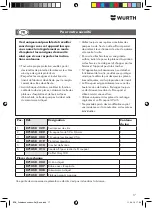
The windscreen removal device is intended for the
removal of windscreens from motor vehicles.
The user is liable for all damage resulting from
improper use.
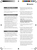
• Windscreen adhesive is more easily cut when it is
warm. If necessary, park the vehicle inside the
workshop to ensure it is at room temperature.
• Remove all covers, trim strips or seals from the
windscreen frame.
• If necessary remove the interior rear view mirror
and any electrical attachments.
• Clean the windscreen so that the suction plates
cannot slip on a film of dirt.
• Protect the dashboard, steering wheel and centre
console with protectors or protective covers, in the
event that the device unexpectedly comes loose
from the windscreen.
• Remove the protective covers from the suction
plates and replace them after use.
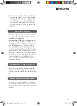
A Using the probe wire 6 puncture the adhesive
bead from the vehicle interior. If possible at a
location on the body where it is possible to
attach the wire fastening. If necessary, protect the
frame with adhesive tape.
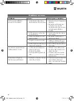
B Thread the end of the cutting wire 2 or cutting
thread 3 through the hole of the wire probe 6
and make a small loop at the end. Pull the wire
probe with the cutting wire carefully into the
interior. The wire length in the interior should
equal 1 x the windscreen diagonal.
C Route the cutting wire 2 or cutting thread 3 from
the outside around the windscreen. When doing
so, ensure that the wire/braid lies properly
Intended use
Preparation for work
Working instructions
positioned below the screen edge on the adhe-
sive bead.
D Secure the cutting wire/cutting thread at a
suitable point using the attachment hook 5. If
possible do not cut the wire 2 or braid 3 off from
the bobbin. This will allow possible subsequent
drawing in of the cutting wire if it breaks.
E Place the screen removal device at the bottom
right in the corner of the windscreen and activate
the pump plunger until the red ring marking can
no longer be seen.
Continually check that the red ring
marking of the pumps does not become
visible and if necessary repeat pump-
ing.
F Guide the wire end in the direction of the arrow
through the spool and bend the end back.
G Using the ratchet lever turn the spool in the
direction shown by the arrow, to wind up the
cutting wire. To do this switch
both
ratchet
reversing levers to 0 (see K). The cutting wire cuts
through the adhesive bead due to its tension.
Always position the protector 4 to protect inner
trim against the cutting wire.
H Once a wire angle
α
of more than 80° to the
cutting direction is reached, the screen removal
device must be moved to the next corner. To do
this switch both ratchet reversing levers to the
neutral position. This unlocks the spool and
ratchet lever, and the wire/braid can be retight-
ened.
I Release the screen removal device from the
windscreen. To do this raise the pulling lug of the
suction plate so that the vacuum can escape.
Now position the windscreen removal device in
the next corner and secure the suction plate by
pumping on the windscreen.
BDA_Scheibenaustrenn-Set_Basic.indd 10
11.09.14 17:34
Summary of Contents for 0714 58 229
Page 3: ...3 i A C E B D F BDA_Scheibenaustrenn Set_Basic indd 3 11 09 14 17 34 ...
Page 4: ...4 Position O 2 3 4 2 3 i G I K H J BDA_Scheibenaustrenn Set_Basic indd 4 11 09 14 17 34 ...
Page 109: ...109 BDA_Scheibenaustrenn Set_Basic indd 109 11 09 14 17 34 ...
Page 110: ...110 BDA_Scheibenaustrenn Set_Basic indd 110 11 09 14 17 34 ...
Page 111: ...111 BDA_Scheibenaustrenn Set_Basic indd 111 11 09 14 17 34 ...


