background image

TRANSMISSION

M6060, M7060, WSM

2-S27

[4]  SEPARATING CLUTCH HOUSING CASE FROM TRANSMISSION 

CASE

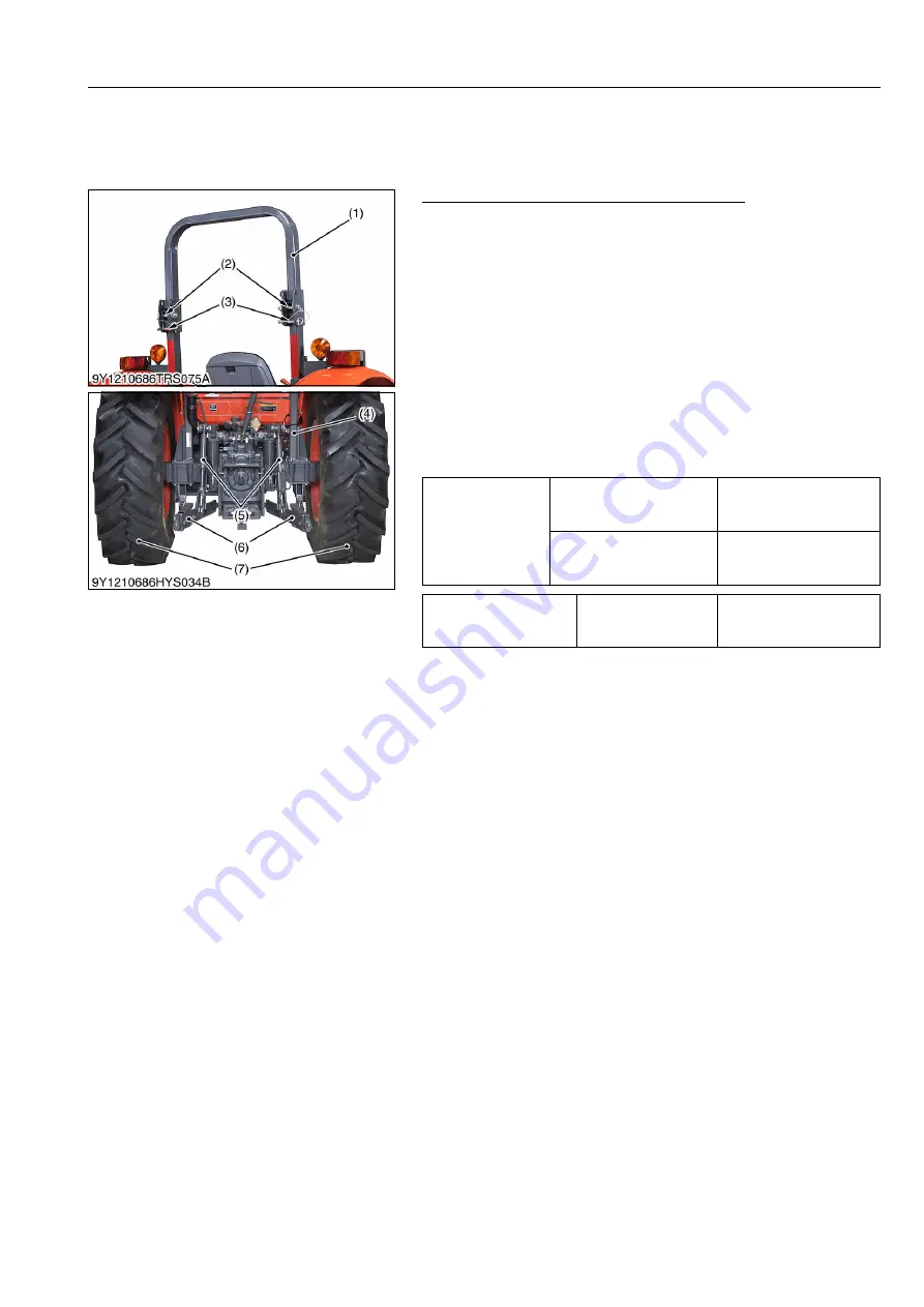
(1)  Preparation for ROPS Model

ROPS, Lower Link, Lift Rod and Rear Wheel

1. Loosen the ROPS under frame (4) mounting screws. (Do not

remove screws.)

2. Remove the ROPS upper frame (1).
3. Remove the lift rod (5) and lower link (6).
4. Chock the front wheels and place the disassembling stand

under the transmission case.

5. Remove the both rear wheels (7) and then place the

disassembling stand under the rear axle case.

6. Remove the fuel tank.

(When reassembling)

• To assemble the ROPS, fix the upper frame with screw (2) and

pin (3) temporarily, then tighten the under frame screws evenly
with specified torque.

• Adjust the upper frame does not fall down with screw (2).

9Y1210828TRS0034US0

Tightening torque

Rear wheel mounting nut

260 to 304 N·m
26.5 to 31.0 kgf·m
191.8 to 224.2 lbf·ft

ROPS under frame 
mounting screw (M16, 9T)

260 to 304 N·m
26.5 to 31.0 kgf·m
192 to 224 lbf·ft

ROPS upper frame lift up 
force at center of upper 
frame

Reference value

246 to 284 N
25.0 to 29.0 kgf
55.2 to 63.9 lbf

(1) ROPS Upper Frame
(2) Screw
(3) Pin
(4) ROPS Under Frame

(5) Lift Rod
(6) Lower Link
(7) Rear Wheel

KiSC issued 08, 2013 A 

Summary of Contents for M6060

Page 1: ...M6060 M7060 WORKSHOP MANUAL TRACTOR KiSC issued 08 2013 A...

Page 2: ...on of Workshop Manual Code No 9Y021 01870 9Y021 18200 for the diesel engine tractor mechanism that this workshop manual does not include Servicing This section primarily contains information below Tro...

Page 3: ...I INFORMATION KiSC issued 08 2013 A...

Page 4: ...CONTENTS 1 SAFETY FIRST I 1 2 SAFETY DECALS I 4 3 SPECIFICATIONS I 10 4 TRAVELING SPEEDS I 14 5 DIMENSIONS I 15 INFORMATION KiSC issued 08 2013 A...

Page 5: ...in disengaged positions Do not start the engine when you stay on the ground Start the engine only from operator s seat WSM000001INI0015US0 SAFETY FIRST This symbol the industry s Safety Alert Symbol i...

Page 6: ...you disconnect hydraulic or fuel lines Tighten all connections before you apply the pressure Do not open a fuel system under high pressure The fluid under high pressure that stays in fuel lines can ca...

Page 7: ...ions when you discard oil fuel coolant electrolyte and other dangerous waste WSM000001INI0007US0 PREVENT ACID BURNS Keep electrolyte away from your eyes hands and clothing Sulfuric acid in battery ele...

Page 8: ...safety decals pictorial safety labels are installed on the machine If a decal becomes damaged illegible or is not on the machine replace it The decal part number is listed in the parts list WSM000001I...

Page 9: ...INFORMATION M6060 M7060 WSM I 5 9Y1210828INI0002US0 KiSC issued 08 2013 A...

Page 10: ...INFORMATION M6060 M7060 WSM I 6 9Y1210828INI0003US0 KiSC issued 08 2013 A...

Page 11: ...INFORMATION M6060 M7060 WSM I 7 CABIN Model 9Y1210828INI0004US0 KiSC issued 08 2013 A...

Page 12: ...INFORMATION M6060 M7060 WSM I 8 9Y1210828INI0005US0 KiSC issued 08 2013 A...

Page 13: ...y with a soft cloth 3 Replace damaged or missing pictorial safety labels with new labels 4 If a component with pictorial safety label s affixed is replaced with new part make sure new label s is are a...

Page 14: ...2515 mm 99 02 in 2455 mm 96 65 in Wheel base 2110 mm 83 07 in Tread Front 1450 to 1540 mm 57 09 to 60 63 in 1365 to 1415 mm 53 74 to 55 71 in Rear 1415 to 1735 mm 55 71 to 68 31 in 1545 to 1740 mm 60...

Page 15: ...Noise at the operator s ear 5 85 3 dB A Noise of the tractor in motion 6 90 dB A Value of the vibration level 7 Grammer MSG95A 721 Light driver 1 24 m s2 124 cm s2 0 126 G Heavy driver 1 1 m s2 110 cm...

Page 16: ...57 09 to 60 63 in 1365 to 1415 mm 53 74 to 55 71 in Rear 1415 to 1735 mm 55 71 to 68 31 in 1545 to 1740 mm 60 83 to 68 30 in Minimum ground clearance 390 mm 15 4 in 330 mm 13 0 in Weight 2725 kg 6008...

Page 17: ...0 3 dB A Noise of the tractor in motion 6 80 dB A Value of the vibration level 7 Grammer MSG95A 721 Light driver 1 24 m s2 124 cm s2 0 126 G Heavy driver 1 1 m s2 110 cm s2 0 11 G Grammer DS85H 90 Lig...

Page 18: ...0 99 L 1 2 6 1 6 2 4 1 5 2 3 7 2 3 3 3 2 0 3 4 7 2 9 4 3 2 7 4 6 1 3 8 5 5 3 4 5 7 7 4 8 7 1 4 4 6 10 2 6 34 9 4 5 8 H 1 12 3 7 64 11 3 7 02 2 17 4 10 8 16 0 9 94 3 22 5 14 0 20 6 12 8 4 28 9 18 0 26...

Page 19: ...INFORMATION M6060 M7060 WSM I 15 5 DIMENSIONS ROPS Model 9Y1210828INI0011US0 KiSC issued 08 2013 A...

Page 20: ...INFORMATION M6060 M7060 WSM I 16 CABIN Model 9Y1210828INI0012US0 KiSC issued 08 2013 A...

Page 21: ...G GENERAL KiSC issued 08 2013 A...

Page 22: ...METRIC SCREWS BOLTS AND NUTS G 17 5 AMERICAN STANDARD SCREWS BOLTS AND NUTS WITH UNC OR UNF THREADS G 17 6 PLUGS G 17 6 MAINTENANCE G 18 7 CHECK AND MAINTENANCE G 21 1 DAILY CHECK G 21 2 CHECK POINTS...

Page 23: ...G 93 1 Front Wheels G 93 2 Adjusting Front Wheel Turning Stopper Bolt For SPAIN Model G 95 3 Rear Wheels G 96 3 WHEEL HUB G 98 4 TIRE LIQUID INJECTION G 98 10 IMPLEMENT LIMITATIONS G 102 1 TRAILER LOA...

Page 24: ...local KUBOTA distributor always specify engine serial number tractor serial number and hourmeter reading 9Y1210828GEG0001US0 1 Tractor Identification Plate 2 Tractor Serial Number 3 Engine Serial Num...

Page 25: ...ays specify engine serial number tractor serial number and hourmeter reading 9Y1210828GEG0002US0 1 Tractor Identification Plate 2 CABIN Identification Plate CABIN Serial Number 3 Tractor Serial Number...

Page 26: ...ear Alphabet or Number Year 1 2001 F 2015 2 2002 G 2016 3 2003 H 2017 4 2004 J 2018 5 2005 K 2019 6 2006 L 2020 7 2007 M 2021 8 2008 N 2022 9 2009 P 2023 A 2010 R 2024 B 2011 S 2025 C 2012 T 2026 D 20...

Page 27: ...the DPF muffler full assembly It shows the month and year of manufacture as below To be continued 1 DPF Muffler Full Assembly Part Number and Serial Number 2 Body DPF Outlet Part Number and Serial Nu...

Page 28: ...2012 T 2026 D 2013 V 2027 E 2014 Month DPF Muffler Full Assembly Lot Number January A0001 A9999 B0001 BZ999 February C0001 C9999 D0001 DZ999 March E0001 E9999 F0001 FZ999 April G0001 G9999 H0001 HZ99...

Page 29: ...ngines may result in emission levels out of compliance with the original E4B design and EPA or other applicable regulations Please refer to the emission label located on the engine head cover to ident...

Page 30: ...ing pins their splits must face the direction from which a force is applied See the figure left side To prevent damage to the hydraulic system use only specified fluid or equivalent Clean the parts be...

Page 31: ...y to modify or remodel any electrical parts and wiring When removing the battery cables disconnect the negative cable first When installing the battery cables connect the positive cable first WSM00000...

Page 32: ...where sag be required WSM000001GEG0068US0 In installing a part be careful not to get wiring caught by it WSM000001GEG0069US0 After installing wiring check protection of terminals and clamped condition...

Page 33: ...recharge the battery remove it from the machine Before you recharge remove cell caps Recharge in a well ventilated place where there is no open flame nearby as hydrogen gas and oxygen are formed WSM0...

Page 34: ...emale connector being too open WSM000001GEG0076US0 Make sure that plastic cover is large enough to cover whole connector WSM000001GEG0077US0 5 HANDLING OF CIRCUIT TESTER Use tester correctly following...

Page 35: ...s symbol of shows color with stripe s An example Red stripe on white color W R WSM000001GEG0079US0 Color of wiring Color code Black B Brown Br Green G Gray Gy or Gr Blue L Light Green Lg Orange Or Pin...

Page 36: ...anti freeze Recovery tank 1 0 L 1 1 U S qts 0 9 Imp qts 3 Washer liquid 1 3 L 1 4 U S qts 1 1 Imp qts Automobile washer liquid 4 Engine crankcase with filter 12 L 12 7 U S qts 10 6 Imp qts API Servic...

Page 37: ...gines in industrial and heavy mobile service SAE J313 JUN87 Transmission Oil KUBOTA Super UDT 2 For an enhanced ownership experience we highly recommend Super UDT 2 to be used instead of standard hydr...

Page 38: ...29 to 33 32 to 34 3 2 to 3 5 24 to 25 48 to 55 4 9 to 5 7 36 to 41 40 to 44 4 0 to 4 5 29 to 32 61 to 70 6 2 to 7 2 45 to 52 M12 63 to 72 6 4 to 7 4 47 to 53 78 to 90 7 9 to 9 2 58 to 66 63 to 72 6 4...

Page 39: ...00 21 7 to 28 9 10 t1 0 39 3 to 49 0 4 00 to 5 00 29 0 to 36 1 12 t1 5 49 1 to 68 6 5 00 to 7 00 36 2 to 50 6 15 t1 6 108 to 117 11 0 to 12 0 79 6 to 86 7 18 t1 6 108 to 117 11 0 to 12 0 79 6 to 86 7...

Page 40: ...to 11 5 16 3 to 19 7 1 67 to 2 00 12 0 to 14 6 5 16 23 1 to 27 7 2 36 to 2 82 17 0 to 20 5 33 to 39 3 4 to 3 9 25 to 28 3 8 48 to 56 4 9 to 5 7 36 to 41 61 to 73 6 3 to 7 4 45 to 53 1 2 110 to 130 11...

Page 41: ...t Replace every 1 year G 38 10 Fuel line Check every 100 Hr G 29 Replace every 2 years G 42 11 Parking brake cable Adjust every 100 Hr G 29 Replace every 2 years G 43 12 Parking brake Check every 100...

Page 42: ...year G 39 37 EGR pipe Check every 1 year G 39 38 Cooling system Flush every 2 years G 40 39 Coolant Flush every 2 years G 40 40 PCV Positive Crankcase Ventilation valve hose Replace every 2 years G 4...

Page 43: ...ery condition by reading the indicator annually 9Y1210828GEG0009US0 No Item Service Interval After since Refer ence page 50 100 150 200 250 300 350 400 450 500 550 600 650 700 1 Inner air filter Clean...

Page 44: ...PS model 12 Check and clean the radiator screen grill oil cooler and battery mount CABIN model 13 Check and clean the air conditioner condenser screen CABIN model 14 Check the DPF muffler 15 Check the...

Page 45: ...engine before changing oil filter cartridge Allow engine to cool down sufficiently oil can be hot and can burn 1 Remove the oil filter 1 2 Put a film of clean engine oil on rubber seal of new filter 3...

Page 46: ...huttle shift lever 1 to the neutral position 5 Turn the key to START position 6 The engine must not crank 7 If it cranks inspect the safety switch Test 3 Checking Operator Presence Control OPC System...

Page 47: ...be early wear 9Y1210828GEG0016US0 Tightening torque Front wheel mounting nut M16 259 9 to 304 0 N m 26 5 to 31 0 kgf m 191 7 to 224 2 lbf ft Rear wheel mounting nut M16 259 9 to 304 0 N m 26 5 to 31...

Page 48: ...very explosive Wear eye protection and rubber gloves when working around battery 1 The original battery is maintenance free type battery Non refillable type When the performance becomes low inspect t...

Page 49: ...ive to the negative then recharge in the standard fashion 2 A boost charge is only for emergencies It will partially charge the battery at a high rate and in a short time When using a boost charged ba...

Page 50: ...primary element 2 Once a year or after every six times of cleaning whichever comes first NOTE Check to see if the evacuator valve is blocked with dust IMPORTANT The air cleaner uses a dry element neve...

Page 51: ...ension 1 Stop the engine and remove the key 2 Apply moderate thumb pressure 98 N 10 kgf 22 1 lbf to belt between pulleys 3 If tension is incorrect loosen the alternator mounting bolts and using a leve...

Page 52: ...If the fuel line is removed be sure to properly bleed the fuel system See page G 44 9Y1210828GEG0022US0 Checking Gear Locked Parking Brake 1 To check and adjusting for the gear locked parking brake r...

Page 53: ...ition lubricate grease fittings more often 9Y1210828GEG0025US0 1 Battery Terminals 2 Grease Fitting Front Axle Support 3 Grease Fitting Front Axle Support 4 Grease Fitting Front Axle Gear Case Support...

Page 54: ...ce and keep the engine unloaded idling 2 Do not stop the engine suddenly but stop it after about 5 minutes of unloaded idling 3 Keep yourself well away from the machine for further 10 minutes or while...

Page 55: ...fuel tank 1 to let sediments impurities and water out of the tank Finally tighten up the plug IMPORTANT If the fuel contains impurities such as water drain the fuel tank at shorter intervals Drain the...

Page 56: ...deformed dust may enter into the air conditioner which may cause damage and malfunction 9Y1210828GEG0032US0 Checking Air Conditioner Condenser CABIN Model 1 Loosen the wing nut 1 2 Hold the handle 2...

Page 57: ...drain plug 1 at the bottom of the transmission case and drain the oil completely into the oil pan 2 After draining reinstall the drain plug 1 3 Remove the two oil filters 2 4 Wipe off metal fillings w...

Page 58: ...ont Axle Pivot 1 If the front axle pivot pin adjustment is not correct front wheel vibration can occur causing vibration in the steering wheel Adjusting Procedure 1 Loosen the lock nut 1 tighten the a...

Page 59: ...e drain plug 3 Fill with the new KUBOTA SUPER UDT fluid up to the upper notch on the dipstick 2 Refer to 4 LUBRICANTS FUEL AND COOLANT on page G 13 4 After running the engine for a few minutes stop it...

Page 60: ...ugs reinstall filling plugs and check plugs 9Y1210828GEG0042US0 10 CHECK POINTS OF EVERY 1500 HOURS Checking Fuel Injection Nozzle Injection Pressure 1 Refer to the Diagnosis Manual 9Y110 01990 2 Use...

Page 61: ...S0 Checking Supply Pump See page 1 S41 9Y1210828GEG0047US0 Checking EGR System See page 1 S17 9Y1210828GEG0048US0 Cleaning DPF Muffler Refer to the DPF Handling Manual 9Y111 08131 9Y1210828GEG0049US0...

Page 62: ...ge or fatigue Replace them if they are deteriorated 9Y1210828GEG0052US0 Checking Exhaust Manifold See page 1 S16 9Y1210828GEG0053US0 Checking DPF Differential Pressure Sensor Pipe See page 1 S21 9Y121...

Page 63: ...lean water and anti freeze until the coolant level is just below the radiator cap Install the radiator cap 2 securely 7 Fill with clean water and anti freeze up to the upper line of recovery tank 3 8...

Page 64: ...e cylinders and radiator If the ambient temperature falls below 0 C or before a long term storage let out coolant completely or mix fresh water with long life coolant and fill the radiator and reserve...

Page 65: ...poration add water only to keep the antifreeze mixing ratio less than 50 In case of leakage add antifreeze and water in the specified mixing ratio before filling in to the radiator 9Y1210828GEG0055US0...

Page 66: ...e 4 S4 9Y1210828GEG0066US0 Replacing Equalizer Kit To check and adjusting for brake pedal See page 4 S4 9Y1210828GEG0067US0 Replacing Brake Seal 1 and 2 To check and adjusting for brake pedal See page...

Page 67: ...around 1500 min 1 rpm position If engine does not start try it several times at 30 second intervals 4 Accelerate the engine to remove the small portion of air left in the fuel system 5 If air still r...

Page 68: ...ake any necessary repairs Failure to follow this procedure may result in serious damage to the tractor electrical system Protected Circuit 9Y1210828GEG0073US0 Fuse No Capacity A Protected circuit 1 15...

Page 69: ...art 2 Remove the bolt from fuse box Bolt fixed slow blow fuse Pull out the fuse from the fuse box Non bolt fixed slow blow fuse 3 Replace with a new one of the same capacity 9Y1210828GEG0074US0 No Cap...

Page 70: ...ical system Protected Circuit Fuse 9Y1210828GEG0075US0 Fuse I D Capacity A Protected circuit 1 5 Radio 2 5 Air Conditioner Control 3 15 Wiper 4 10 Alternator PTO Engine 5 5 Meter 6 10 Turn Signal Stop...

Page 71: ...fuse Pull out the fuse from the fuse box Non bolt fixed slow blow fuse 3 Replace with a new one of the same capacity 9Y1210828GEG0076US0 No Capacity Protected circuit Type 1 30 A Electrical outlet Bo...

Page 72: ...he reverse order Other lights 1 Remove the lens and replace the bulb IMPORTANT Be sure to use a new bulb of the specified wattage Never touch the bulb surface glass with bare hands Fingerprints for ex...

Page 73: ...is indicated that the amount of refrigerant is extremely low inspect and charge See page 9 S14 Checking Procedure 1 Run the air conditioner in the following conditions Engine speed About 1500 min 1 r...

Page 74: ...o measure the diesel engine compression and to make a decision for a large overhaul if necessary WSM000001GEG0113US0 Oil Pressure Tester Code No 07916 32032 Application To measure the engine oil press...

Page 75: ...669 in M 1 0 mm 0 039 in C 16 0 mm dia 0 630 in dia P0 5 N 17 0 mm 0 669 in D 13 0 mm dia 0 512 in dia O 61 5 mm 2 42 in E 9 5 mm dia 0 37 in dia P 15 0 mm 0 591 in F M8 x 1 0 Q 10 0 mm 0 394 in G 6 5...

Page 76: ...4 7244 in D 27 4 mm dia 1 0787 in dia E 30 95 mm dia 1 2185 in dia F 20 mm dia 0 7874 in dia a 6 3 m 250 in b 6 3 m 250 in C1 Chamfer 1 0 mm 0 039 in C2 Chamfer 2 0 mm 0 079 in A 157 mm 6 181 in B 14...

Page 77: ...in C 45 mm 1 8 in D 20 mm dia 0 79 in dia E 11 7 to 11 9 mm dia 0 461 to 0 468 in dia F 6 50 to 6 60 mm dia 0 256 to 0 259 in dia G 25 mm dia 0 98 in dia H 6 70 to 7 00 mm dia 0 264 to 0 275 in dia I...

Page 78: ...in F 10 0 mm 0 394 in G 95 0 mm dia 3 74 in dia H 78 900 to 79 100 mm dia 3 1063 to 3 1141 in dia I 57 971 to 57 990 mm dia 2 2824 to 2 2830 in dia J 50 0 mm dia 1 97 in dia K 15 0 mm dia 0 591 in dia...

Page 79: ...0 394 in G 120 mm dia 4 72 in dia H 100 90 to 101 10 mm dia 3 9725 to 3 9803 in dia I 86 966 to 86 988 mm dia 3 4239 to 3 4247 in dia J 79 0 mm dia 3 11 in dia K 15 0 mm dia 0 591 in dia L 30 0 mm di...

Page 80: ...gh hole F 61 0 mm 2 40 in G 18 7 mm 0 736 in H 30 90 to 31 70 mm 1 217 to 1 248 in a 0 30 mm radius 0 012 in radius C0 5 Chamfer 0 50 mm 0 020 in C1 Chamfer 1 0 mm 0 039 in C2 Chamfer 2 0 mm 0 079 in...

Page 81: ...dia 3 2276 to 3 2277 in dia U 163 mm 6 42 in F 6 0 mm 0 24 in V 8 0 mm dia 0 31 in dia G 23 5 mm 0 925 in W 33 475 to 33 525 mm 1 3180 to 1 3198 in H 29 5 mm 1 16 in a Ra 1 6 a I 58 0 mm 2 28 in b 0 5...

Page 82: ...ol is not provided so make it referring to the figure 9Y1210828GEG0090US0 A 126 6 mm 4 984 in B 49 1 mm 1 93 in C 37 5 mm 1 48 in D 20 mm 0 79 in E 14 mm dia 0 55 in dia F 14 mm dia 0 55 in dia G 14 m...

Page 83: ...82 036 to 82 071 mm dia 3 2298 to 3 2311 in dia G 77 0 mm dia 3 03 in dia H 57 0 mm dia 2 24 in dia I 35 0 mm dia 1 38 in dia J 30 0 mm dia 1 18 in dia K 84 0 mm dia 3 31 in dia L 3 5 mm 0 14 in M 3 0...

Page 84: ...the figure 9Y1210828GEG0092US0 A 30 0 mm dia 1 18 in dia B 40 0 mm dia 1 57 in dia C 24 8 to 25 2 mm dia 0 977 to 0 992 in dia D 18 4 to 18 5 mm dia 0 725 to 0 728 in dia E 8 80 to 8 90 mm 0 347 to 0...

Page 85: ...ading rotatino sensor signal NOTE This special tool is not provided so make it referring to the figure 9Y1210828GEG0093US0 1 9V Battery 2 Switch 3 3 Terminal Regulator 4 LED 5 Clip Red 6 Clip Black A...

Page 86: ...mm 6 4173 in F 6 mm 0 2362 in V 8 mm dia 0 315 in dia G 23 5 mm 0 9252 in W 33 475 to 33 525 mm 1 3180 to 1 3198 in H 29 5 mm 1 1614 in a Ra 1 6 a I 58 mm 2 2835 in b 0 5 mm radius 0 0197 in radius J...

Page 87: ...m 0 827 in D 204 mm 8 032 in E 102 mm 4 016 in F 15 mm 0 591 in G 59 mm 2 323 in H 14 mm dia 0 551 in dia I 80 mm radius 3 150 in radius J 70 mm 2 756 in K 460 mm 18 110 in L 270 mm 10 630 in M 6 mm 0...

Page 88: ...in H 48 8 to 48 9 mm dia 1 9213 to 1 9252 in dia a 3 mm 0 1181 in I 0 523 rad 30 b 35 mm 1 3780 in J 40 mm dia 1 5748 in dia c 53 mm 2 0866 in K 20 mm dia 0 7874 in dia d 3 mm 0 1181 in L 34 9 to 35 0...

Page 89: ...H 20 mm dia 0 7874 in dia c 12 mm 0 4724 in I 46 mm dia 1 8110 in dia d 12 mm 0 4724 in J 34 mm 1 3386 in e 4 mm 0 1575 in K 99 mm 3 8976 in f 35 mm 1 3780 in L 34 9 to 35 0 mm 1 3740 to 1 3780 in g...

Page 90: ...4 in H 46 mm dia 1 8110 in dia c 4 mm 0 1575 in I 34 mm 1 3386 in d 3 mm 0 1181 in J 99 mm 3 8976 in e 35 mm 1 3780 in K 34 9 to 35 0 mm 1 3740 to 1 3780 in f 53 mm 2 0866 in L 5 mm 0 1969 in g 3 mm 0...

Page 91: ...8 to 48 9 mm dia 1 9213 to 1 9252 in dia V 50 mm 1 9685 in G 40 mm dia 1 5748 in dia W 0 698 rad 40 H 0 523 rad 30 X 2 mm 0 0787 in I 1 5 mm 0 0591 in Y 3 mm 0 1181 in J 20 mm dia 0 7874 in dia a 0 8...

Page 92: ...582 in dia 0 2756 in depth c 18 mm 0 7087 in I 20 mm dia 0 7874 in dia d 4 mm 0 1575 in J 46 mm dia 1 8110 in dia e 12 mm 0 4724 in K 34 9 to 35 0 mm dia 1 3740 to 1 3780 in dia f 15 mm 0 5906 in L 8...

Page 93: ...9 to 35 0 mm dia 1 3740 to 1 3780 in dia a 50 mm 1 9685 in I 4 000 to 4 018 mm dia 7 mm depth 0 1575 to 0 1582 in dia 0 2756 in depth b 0 698 rad 40 J 1 2 mm 0 0472 in c 2 mm 0 0787 in K 5 mm 0 1969...

Page 94: ...e Application This allows easy testing of hydraulic system WSM000001GEG0036US0 Adaptor Set for Flow Meter Code No 07916 54031 Application Use for test of the hydraulic system WSM000001GEG0037US0 1 Gau...

Page 95: ...Bleeder Code No 07916 54001 Application This allows easy air bleed of the hydraulic brake WSM000001GEG0046US0 Relief Valve Setting Pressure Adaptor G Code No 07916 52751 Application This allows easy...

Page 96: ...ing Restrictor NOTE The following special tool is not provided so make it referring to the figure 9Y1210828GEG0103US0 A 120 mm 4 72 in B 12 mm 0 72 in C M10 P1 25 D 30 mm 1 18 in E M16 P1 5 F 10 mm 0...

Page 97: ...gure 9Y1210828GEG0104US0 A 120 mm 4 72 in B 14 5 mm dia 0 57 in dia C 60 mm dia 2 36 in dia D Chamfer 5 mm 0 20 in E M14 P1 5 F 25 mm 0 98 in G 40 mm 1 57 in H 450 mm 17 72 in I 14 mm dia 0 55 in dia...

Page 98: ...with sliding hammer NOTE The following special tool is not provided so make it referring to the figure 9Y1210828GEG0105US0 Front axle bevel pinion shaft Hydraulic pump drive gear pin A M6 P1 0 M8 P1...

Page 99: ...3 97 in D 54 to 60 mm full spline 2 12 to 2 36 in full spline E 22 4 to 28 4 mm 0 88 to 1 11 in F 4 to 6 mm 0 16 to 0 23 in G 0 52 rad 30 H Involute spline refer to below I Chamfer 3 0 mm 0 12 in J 1...

Page 100: ...10mm 7 Washer M5 8 Spring Pin 5 0 mm Dia L16 mm A 8 mm 0 3 in B 40 mm 1 6 in C 16 mm 0 63 in D 8 mm 0 3 in E 16 mm 0 63 in F 5 2 mm dia 0 20 in dia G 5 70 to 5 90 mm 0 225 to 0 232 in H 80 mm 3 1 in A...

Page 101: ...0 039 in E 35 mm 1 4 in M Chamfer 0 5 mm 0 02 in F Radius 5 mm 0 2 in N 7 mm 0 3 in G 10 00 to 10 27 mm 0 3937 to 0 4043 in O 20 mm 0 79 in H 20 mm 0 79 in X X X View direction A 330 mm 13 0 in G 6 00...

Page 102: ...d so make it referring to the figure 9Y1210828GEG0112US0 A 170 mm 6 69 in B 130 mm 5 12 in C 63 5 mm 2 5 in D 40 mm radius 1 57 in radius E 55 mm 2 17 in F 15 mm 0 59 in G 35 mm 1 38 in H 5 mm 0 2 in...

Page 103: ...6 in dia 32 5 mm dia 1 28 in dia D 0 52 rad 30 0 52 rad 30 E 26 0 mm dia 1 02 in dia 32 6 to 33 0 mm dia 1 28 to 1 29 in dia F Involute spline refer to below Involute spline refer to below G Chamfer 1...

Page 104: ...cylinder NOTE The following special tool is not provided so make it referring to the figure 9Y1210828GEG0115US0 A 1045 mm 41 14 in B 1000 mm 29 37 in C 20 mm dia 0 79 in dia D 30 mm dia 1 18 in dia E...

Page 105: ...dia 0 39 in dia B 40 mm 1 58 in O 7 5 mm dia 0 3 in dia C 35 mm 13 8 in P 1 05 rad 60 D 23 to 23 3 mm 0 9055 to 0 9713 in Q 3 mm dia 1 18 in dia E 16 mm 0 63 in R 36 mm 1 18 in F 40 mm dia 1 58 in dia...

Page 106: ...special tool is not provided so make it referring to the figure 9Y1210828GEG0118US0 A 24 mm 0 94 in B 27 7 mm 1 09 in C PS1 4 D 11 mm 0 43 in E 15 mm 0 59 in F 40 mm 1 57 in G 60 mm 2 36 in H 15 mm 0...

Page 107: ...ce A 1 Piece B 2 Piece C 4 Piece D 4 Piece E 2 A 77 0 mm 3 03 in G 600 mm 23 6 in M 60 0 mm 2 36 in B 50 0 mm 2 17 in H 1562 mm 61 50 in N 4 5 mm 0 18 in C 200 mm 7 87 in I 65 0 mm 2 56 in O 8 11 0 mm...

Page 108: ...64 96 in F 4 5 mm 0 18 in B 1200 mm 47 24 in E 50 0 mm 1 97 in G 6 11 0 mm dia 0 433 in dia C 1362 mm 53 62 in 1 Material STKR400 50 50 t45 A 62 0 mm 2 44 in B 90 0 mm 3 54 in C 12 5 mm 0 492 in D 25...

Page 109: ...m dia 0 512 in dia S 60 0 mm 2 36 in D 32 0 mm 1 26 in L 60 0 mm 2 36 in T 4 5 mm radius 0 18 in radius E 16 0 mm 0 630 in M 45 0 mm 1 77 in U 3 5 mm radius 0 14 in radius F 60 0 mm 2 36 in N 30 0 mm...

Page 110: ...mm 0 433 in R 25 0 mm 0 984 in D 264 mm 10 4 in M 61 0 mm 2 40 in S 10 0 mm dia 0 394 in dia E 15 0 mm 0 591 in N 64 5 mm 2 54 in T 4 5 mm 0 18 in F 46 0 mm 1 81 in L 11 0 mm dia 0 433 in dia U Chamf...

Page 111: ...0 Vacuum Pump Code No DENSO 95046 00130 AC220V DENSO 95046 00140 AC240V Application Use to evacuate the air conditioning system WSM000001GEG0044US0 1 Manifold Gauge Assembly 95048 10090 2 Charging Hos...

Page 112: ...not provided so make it referring to the figure 9Y1210828GEG0125US0 A 125 mm 4 92 in H 4 52 rad 120 B 40 mm dia 1 57 in dia I Radius 27 mm Radius 1 06 in C Radius 33 mm Radius 1 30 in J Radius 50 mm R...

Page 113: ...stopper magnet clutch NOTE The following special tool is not provided so make it referring to the figure 9Y1210828GEG0126US0 A 12 mm 0 47 in E 5 5 mm dia 0 22 in dia B 35 mm 1 38 in F 6 5 mm dia 0 26...

Page 114: ...how in the operator s manual IMPORTANT Do not use tires other than those approved by KUBOTA Dual tires are not approved Excessive wear of the tires may occur due to improper gear ratio NOTE When optio...

Page 115: ...kPa 1 4 kgf cm2 20 3 psi 9 5 24 180 kPa 1 8 kgf cm2 26 1 psi 300 70R20 240 kPa 2 4 kgf cm2 34 8 psi 15 0 70 18 360 kPa 3 6 kgf cm2 52 2 psi 8 3R24 310 kPa 3 1 kgf cm2 45 0 psi 9 5R24 160 kPa 1 6 kgf...

Page 116: ...s attach wheels as shown in the figure If not attached as illustrated transmission parts may be damaged When re fitting or adjusting a wheel tighten the bolts to the following torques then recheck aft...

Page 117: ...1539 mm 60 59 in 320 85R20 1450 mm 57 09 in 1537 mm 56 51 in 9 5 24 1444 mm 56 85 in 1498 mm 58 98 in 300 70R20 1454 mm 57 24 in 1540 mm 60 63 in 15 0 70 18 1571 mm 61 85 in 8 3R24 1446 mm 56 93 in 1...

Page 118: ...0131US0 9 5 20 1372 mm 54 02 in 1385 mm 54 53 in 1398 mm 55 04 in 12 5 80 18 1411 mm 55 55 in 320 70R20 1389 mm 54 68 in 1366 mm 53 78 in 1416 mm 55 75 in 9 5 24 1325 mm 52 17 in 300 70R20 1390 mm 54...

Page 119: ...tor 200 m 200 yards and 10 times of shuttle movement by 5 m 5 yards and thereafter according to service interval See page G 24 Disc Manufactured by TITAN INTERNATIONAL INC Disc Other manufactured To b...

Page 120: ...in 1283 mm 50 51 in 1463 mm 57 60 in 1517 mm 59 72 in 1629 mm 64 13 in 1683 mm 66 26 in 270 95R38 1254 mm 49 37 in 1308 mm 51 50 in 1438 mm 56 61 in 1492 mm 59 74 in 1654 mm 65 12 in 1708 mm 67 24 in...

Page 121: ...ide solution injection IMPORTANT Do not fill the front tires with liquid 9Y1210828GEG0134US0 Preparation of Calcium Chloride Solution CAUTION aaa 9Y1210828GEG0135US0 Front wheel hub Rear wheel hub Scr...

Page 122: ...aching Injector 1 Lift the rear tires off the ground 2 Turn the tire so that the air valve is at the top 3 Remove the air valve and attach the injector Code No 07916 52501 9Y1210828GEG0136US0 1 Inject...

Page 123: ...ee at 24 C 11 F Solid at 47 C 53 F Approx 1 5 kg 3 5 lbs CaCl2 per 4 L 1 gal of water Slush free at 47 C 53 F Solid at 52 C 62 F Approx 2 25 kg 5 lbs CaCl2 per 4 L 1 gal of water 380 85R28 178 kg 392...

Page 124: ...ve the air valve and drain liquid liquid can only be drained to the level of the valve and liquid under that level remains inside 4 To drain liquid completely use the injector 1 and direct compressed...

Page 125: ...st a toppling trees primarily in case a rear mounted tree grab crane is mounted at the rear of the tractor b penetrating objects in the operator s enclosure primarily in case a winch is mounted at the...

Page 126: ...mm 91 in Max Weight 800 kg 1760 lbs 6 Bottom Plow Max Size 14 in 3 16 in 2 18 in 1 16 in 3 18 in 2 Max Weight 3 point Hitch Type 450 kg 1000 lbs 550 kg 1200 lbs 7 Disc harrow 3 point Hitch Type Max S...

Page 127: ...ng Capacity 1328 kg 2928 lbs Max Oil Pressure 19 8 MPa 202 kgf cm2 2870 psi 14 Box Blade Max Cutting Width 1820 mm 72 in 2130 mm 84 in Max Weight 450 kg 1000 lbs 550 kg 1200 lbs 15 Back Hoe 2 Max Digg...

Page 128: ...kg 2271 lbs 1120 kg 2469 lbs 1180 kg 2601 lbs 1190 kg 2624 lbs Trailer loading weight max capacity W3 Unbraked towable mass 3000 kg 6614 lbs 3000 kg 6614 lbs 3000 kg 6614 lbs 3000 kg 6614 lbs 3000 kg...

Page 129: ...lbs 890 kg 1960 lbs F 1030 kg 2271 lbs 1100 kg 2425 lbs G 1130 kg 2491 lbs 1200 kg 2646 lbs H 1200 kg 2646 lbs Trailer loading weight max capacity W3 Unbraked towable mass 3000 kg 6614 lbs 3000 kg 66...

Page 130: ...bs D 1340 kg 2954 lbs Trailer loading weight max capacity W3 Unbraked towable mass 3000 kg 6614 lbs 3000 kg 6614 lbs Independently braked mass 5000 kg 11020 lbs 5000 kg 11020 lbs Inertia braked towabl...

Page 131: ...onal Special attention should be made when lifting the load keep the bucket correctly positioned to prevent spillages NOTE Not all risks are listed Refer to front loader operator s manual 9Y1210828GEG...

Page 132: ...1 ENGINE KiSC issued 08 2013 A...

Page 133: ...STON 1 M6 9 BUILT IN DYNAMIC BALANCER 1 M6 3 LUBRICATING SYSTEM 1 M7 1 OIL COOLER 1 M7 4 COOLING SYSTEM 1 M8 1 THERMOSTAT 1 M8 2 BOTTOM BYPASS SYSTEM 1 M9 5 FUEL SYSTEM 1 M10 1 OVERVIEW 1 M10 2 SUPPLY...

Page 134: ...new E CDIS The 07 series DI engine newly adopted ladder frame crankshaft support structure gear train located at flywheel side and coolant evenness distribution type cooling jacket Thus this engine a...

Page 135: ...sion on friction thanks to accuracy of axial concentricity The cylinder is a linerless type which enables good cooling operation less strain and good abrasion resistance 9Y1210828ENM0002US0 2 COOLING...

Page 136: ...rangement helps reduce noise coming from the cylinder head 9Y1210828ENM0004US0 4 CYLINDER HEAD This engine employs four valve system the cylinder head is provided with double intake passage in order t...

Page 137: ...rom the top and bottom to the crankcase 1 3 with each of 10 screws The following objectives are in the 4 screws per each cylinder assembling structure 1 Reduce the load share rate of combustion pressu...

Page 138: ...ies DI engine has two intake valves and two exhaust valves per each cylinder The rocker arm 1 contacts a valve bridge arm 2 instead of the valves stem tip The valve bridge arm 2 then contacts both int...

Page 139: ...9 BUILT IN DYNAMIC BALANCER Engine are sure to vibrate by piston s reciprocation Theoretically three cylinder engines are much less prone to cause vibration than four cylinder ones second inertia etc...

Page 140: ...also warms the cool engine oil shortly after start up As shown in the figure the oil flows inside the connected cooler plate whereas coolant is kept circulating outside the cooler plate thereby cooli...

Page 141: ...cooled by the radiator flows through the water passage which suddenly closes the valve below the thermostat s preset valve closing temperature A repeated cycle of such overshoot 3 and undershoot phen...

Page 142: ...sed and the coolant is allowed to flow through the bypass pipe and to circulate in the engine When the temperature exceeds the thermostat 1 valve opening level the thermostat 1 fully opens itself to p...

Page 143: ...ject the fuel under high pressure via solenoids into each cylinder and an engine ECU that controls them all Various parameters are controlled by the engine ECU such as the amount of fuel from the inje...

Page 144: ...e process the volume of the part enclosed by the teeth of the rotor changes and thus pumps the fuel 9Y1210828ENM0017US0 Regulating Valve The regulating valve controls the fuel feed pressure feed pump...

Page 145: ...ducing the quantity of fuel supplied The solenoid turns ON OFF according to the duty ratio The quantity of fuel supplied to the plunger is in proportion to the size of the cylinder opening 2 Duty rati...

Page 146: ...s exceeds the pressure on the rail side the check ball opens and discharges fuel As soon as the fuel pressure feed is complete the check ball is pressed back by the spring and when it touches the seat...

Page 147: ...o keep the pressure valve closes Fuel discharged by the pressure limiter returns to the fuel tank Rail Pressure Sensor The rail pressure sensor is mounted on the rail detects the pressure inside the r...

Page 148: ...fuse combustion is induced thus reducing particulate matter PM generated by the main injection Injector Architecture Injectors consist of nozzle components nozzle 10 and needle valve 9 a TWV two way v...

Page 149: ...e pressure The drop in the pressure of the control chamber causes the pressure applied to the bottom of the needle valve 5 to become greater than the pressure on the control chamber side and the needl...

Page 150: ...e is registered in the ECU 9Y1210828ENM0027US0 When Replacing an Injector Register the ID code of the replacement injector into the ECU 9Y1210828ENM0028US0 When Replacing the Engine ECU Register the I...

Page 151: ...ure Sensor 16 SCV Suction Control Valve 17 Rail Pressure Sensor 18 Rail 19 Pressure Limiter 20 Injector 21 EGR DC Motor 22 EGR Lift Sensor 23 Intake Throttle Valve 24 Intake Air Pressure Sensor 25 Int...

Page 152: ...al fuel mixture is kept to a minimum mitigating the explosive initial combustion and reducing NOx and noise Fuel Pressure Control The ECU calculates the set fuel injection pressure based on the engine...

Page 153: ...gnal and camshaft position sensor output signal The camshaft pulsar gear rotates once when the crankshaft pulsar gear rotates twice 12 6 rad 720 crank angle There is a gearless section in the cranksha...

Page 154: ...s shaft The motor s shaft opens and closes the valve by changing the rotation of the motor into linear motion via a screw deceleration mechanism 9Y1210828ENM0036US0 2 REED VALVE The reed valves are se...

Page 155: ...g the NOx that is in the exhaust gas of diesel engine The EGR cooler 1 is set between the cylinder head and the EGR valve and returns the cooled exhaust gases to the engine suction side The EGR cooler...

Page 156: ...T0 10 Temperature Sensor DPF Inlet Exhaust Temperature T1 11 Differential Pressure Sensor DPF Differential Pressure P 12 Temperature Sensor DPF Outlet Exhaust Temperature T2 13 Diesel Oxidation Catal...

Page 157: ...regeneration is impossible Regeneration is possible with service tools only Service tools are available among all levels without level 5 Level 5 DPF Cleaning Regeneration is impossible even with serv...

Page 158: ...h spontaneously combusts when exhaust gas temperature is high However while exhaust gas temperature is low PM does not spontaneously combust the pressure differential between the inlet and outlet of t...

Page 159: ...ntake and DPF discharge exhaust temperature needed for the post processing system are measured 9Y1210828ENM0047US0 Differential Pressure Sensor The differential pressure sensor is a sensor that detect...

Page 160: ...oil in the blowby gases that pass through the element 1 and the oil is returned to the oil pan Blowby gases that pass through the element 1 are mixed into the intake upstream from the turbo charger 9...

Page 161: ...l 1 S24 6 Separating Engine From Clutch Housing CABIN Model 1 S26 7 Separating Engine From Front Axle Frame 1 S29 3 DISASSEMBLING AND ASSEMBLING 1 S30 1 External Components 1 S30 2 Turbocharger and EG...

Page 162: ...fuel G 14 The cetane number of fuel is low Replace the specified fuel G 14 Fuel leakage because of loose injection pipe retaining nut Tighten the retaining nut 1 S32 The injector is clogged Replace 1...

Page 163: ...nto the exhaust pipe or suction pipe The oil pipe is clogged or has a damage Examine replace or clean the oil pipe The piston ring seal of the turbocharger is damaged Replace the turbocharger assembly...

Page 164: ...e relief valve does not operate with dirt Repair or replace 1 S45 The oil clearance of the bearings are too much Replace the metal bushing or shaft 1 S52 1 S54 1 S72 1 S73 The oil passage is clogged C...

Page 165: ...o 0 085 mm 0 0022 to 0 0033 in 6 960 to 6 975 mm 0 2741 to 0 2746 in 7 030 to 7 045 mm 0 2768 to 0 2773 in 0 10 mm 0 0039 in Valve Guide Intake and Exhaust I D 7 030 to 7 045 mm 0 2768 to 0 2773 in Va...

Page 166: ...ash Backlash Backlash Backlash 0 041 to 0 139 mm 0 0016 to 0 0055 in 0 041 to 0 134 mm 0 0016 to 0 0053 in 0 041 to 0 134 mm 0 0016 to 0 0053 in 0 041 to 0 134 mm 0 0016 to 0 0053 in 0 041 to 0 129 mm...

Page 167: ...Shaft 1 Journal Balancer Shaft 1 Bearing Oil Clearance O D I D 0 060 to 0 145 mm 0 0024 to 0 0057 in 48 934 to 48 950 mm 1 9265 to 1 9272 in 49 010 to 49 080 mm 1 9295 to 1 9323 in 0 2 mm 0 0079 in Ba...

Page 168: ...in 0 15 mm 0 0059 in Crankshaft Side Clearance Alignment 0 15 to 0 35 mm 0 0059 to 0 013 in 0 50 mm 0 020 in 0 02 mm 0 0008 in Crank Pin to Crank Pin Bearing Crank Pin Oil Clearance O D 0 017 to 0 04...

Page 169: ...ngth 60 0 to 60 5 mm 2 37 to 2 38 in 55 0 mm 2 17 in Item Factory Specification Allowable Limit Fan Alternator Belt ROPS Model Tension 16 to 17 mm 98 N 0 63 to 0 68 in 98 N 10 kgf 22 lbf Fan Alternato...

Page 170: ...il mounting screw M8 1 25 24 to 27 2 4 to 2 8 18 to 20 Injection pipe retaining nut M14 1 5 30 to 40 3 1 to 4 0 23 to 29 Overflow pipe joint screw Cylinder head side M8 M8 11 to 15 1 2 to 1 5 8 2 to 1...

Page 171: ...22 1 5 69 to 78 7 0 to 8 0 51 to 57 Flywheel screw M12 1 25 98 1 to 107 10 0 to 11 0 72 4 to 79 5 Flywheel housing mounting screw 9T M12 1 25 103 to 117 10 5 to 12 0 76 0 to 86 7 Camshaft set screw M8...

Page 172: ...s twice for each cylinder NOTE Examine the compression pressure with the specified valve clearance Always use a fully charged battery for you do this test Variances in cylinder compression values must...

Page 173: ...pecifications adjust with the adjusting screw 1 and tighten the lock nut 2 of the adjusting screw NOTE After you adjust the valve clearance tighten the lock nut 2 of the adjusting screw 9Y1210828ENS00...

Page 174: ...level Oil pump Oil strainer Oil filter cartridge Oil passage Oil clearance Relief valve When reassembling After you examine the oil pressure of the engine tighten its oil pressure switch to the specif...

Page 175: ...on 9Y1210828ENS0007US0 Alternator Belt Tension 1 Measure the deflection L depressing the belt halfway between the pulleys at specified force 98 N 10 kgf 22 lbf 2 If the measurement is not within the f...

Page 176: ...tester on the radiator cap 2 Attach a radiator tester Apply the specified pressure of 88 kPa 0 9 kgf cm2 13 psi 3 Check if the pressure drop to less than 59 kPa 0 6 kgf cm2 9 psi in 10 seconds 4 If t...

Page 177: ...xhaust port 3 and the inlet port 5 side of the turbine housing 1 for exhaust gas leakage 2 If you find a gas leakage tighten the screws and nuts again or replace the gasket 2 4 6 with a new one 9Y1210...

Page 178: ...t passage 1 Block the EGR cooler exhaust gas inlet 1 EGR cooler exhaust gas outlet 2 and the coolant outlet 3 2 Attach an air hose to the EGR cooler coolant inlet 4 and then submerge it in a water tan...

Page 179: ...nnecting positive cable first When reassembling Tighten the negative terminal nut 4 until the stopper 3 contacts to the negative terminal 5 Tighten the positive terminal nut 7 so that the clearance L...

Page 180: ...th the one of muffler band 1 Be sure that the center line of under muffler pipe 4 is in accordance with the one of the under muffler pipe 5 9Y1210828ENS0019US0 1 Muffler Band 2 Muffler Pipe 3 Welded S...

Page 181: ...nuts 5 bolts 3 4 7 and 8 to the muffler mount bracket 2 Tighten the muffler mounting bolt 1 3 firmly 3 Tighten the muffler mounting bolt 3 7 firmly 4 Tighten the muffler mounting bolt 4 8 firmly 5 Tig...

Page 182: ...time by connecting the service tool Diagmaster When installing and removing the muffler full assembly DPF make sure that the temperature sensor differential pressure sensor and differential pressure...

Page 183: ...position Tighten bolts and nuts to their specified torque Also tighten the temperature sensor tightening nut or the differential pressure pipe tightening nut to the specified torque with crowfoot wre...

Page 184: ...shaft 5 and pinion shaft Tap in the roll pins 2 as shown in figure 9Y1210828ENS0023US0 Front Axle Support as a Unit 1 Make sure the clutch housing case and front frame are securely mounted on the dis...

Page 185: ...teering hoses 1 When reassembling 9Y1210828ENS0026US0 Inlet air hose and coolant hose 1 Disconnect the inlet air hose 1 2 Disconnect the coolant hose 2 9Y1210828ENS0027US0 Connector and Wire Harness 1...

Page 186: ...w one please record the serial number of new engine and the parts number and serial number of DPF Full Assembly which is incorporate with its new engine When reassembling Apply molybdenum disulphide T...

Page 187: ...he compressor 7 toward counterclockwise viewing from forward side 6 Remove the mounting bolts 8 of the compressor stay 7 Turn the steering wheel to left 8 Remove the flying nut 9 and slide out the con...

Page 188: ...3 5 Disconnect the return hose 4 6 Remove the power steering controller 1 When reassembling When reassembling the power steering controller see page 6 S7 9Y1210828ENS0033US0 Power Steering Pipe and fu...

Page 189: ...ling port 2 3 Remove the floor mat 1 3 and mat 2 4 4 Remove the floor cover 5 the duct band 7 and the front duct 8 5 Disconnect the connectors 6 6 Pull out these connectors from cabin 9Y1210828ENS0035...

Page 190: ...gasket Three Bond 1211 or equivalent to joint face of the engine and clutch housing 9Y1210828ENS0036US0 7 Separating Engine From Front Axle Frame Separating Engine from Front Axle Frame 1 Disconnect...

Page 191: ...es After you replace the turbocharger assembly fill clean engine oil through the oil filter port of the turbocharger Before you start the engine make sure that the air cleaner is in the correct positi...

Page 192: ...ones 9Y1210828ENS0042US0 Intake Throttle Valve 1 Remove the cover 1 and the air cleaner flange 2 2 Remove the intake throttle valve 3 NOTE Do not disassemble the intake throttle valve When reassembli...

Page 193: ...ly to their specified torques 9Y1210828ENS0044US0 Coolant Temperature Sensor 1 Remove the coolant temperature sensor 1 When reassembling Replace the gaskets with new ones 9Y1210828ENS0045US0 Tightenin...

Page 194: ...oving the hose from the boost sensor 1 Remove the hose 3 from the boost sensor 1 2 Remove the boost sensor mounting screw 2 3 Remove the boost sensor 1 When reassembling Replace the gaskets with new o...

Page 195: ...t of cylinder head cover with a new one Adjust the direction of the ditch to the terminal side when the seal 5 is installed in the glow plug 1 After installing the glow plug 1 make sure that the seal...

Page 196: ...t screw 4 Tighten the injector clamp nuts securely to their specified torques Tighten the overflow pipe joint screws 4 securely to their specified torques After installing the overflow pipe in order t...

Page 197: ...he valve 4 7 Check the decreased pressure after 4 seconds NOTE If the decreased pressure is higher than 0 001 MPa 0 01 kgf cm2 0 1 psi it means that there is fuel leakage Replace the gasket 5 then che...

Page 198: ...3 face the mark 4 to intake side IMPORTANT After installing the rocker arm adjust the valve clearance 9Y1210828ENS0053US0 Injector Oil Seal and Injection Pipe Oil Seal If necessary 1 Remove the injec...

Page 199: ...in the sequence of a to j after applying engine oil Be sure to adjust the valve clearance Refer to the Valve Clearance It is not necessary to retighten the cylinder head mounting screw after running...

Page 200: ...figure and get the average of the measurements 2 Use the table below to select an applicable cylinder head gasket 1 9Y1210828ENS0056US0 Notch of Cylinder Head Gasket Thickness of cylinder head gasket...

Page 201: ...ch 7 end downward at the cylinder head side B 9Y1210828ENS0057US0 5 Thermostat Thermostat Assembly 1 Remove the thermostat cover mounting screws and remove the thermostat cover 1 2 Remove the thermost...

Page 202: ...en the piston of the 4th cylinder is TDC If they do not mesh rotate the flywheel counterclockwise one revolution 3 Make a temporary mark 5 with a white paint marker pen on the tooth of idle gear 6 NOT...

Page 203: ...ow cover 1 NOTE When replacing the supply pump with a new one use the diagnosis tool to conduct learning of discrepancies in the new supply pump 9Y1210828ENS0059US0 Tightening torque Supply pump mount...

Page 204: ...pulsar gear 4 When reassembling Install the crankshaft position pulsar gear 4 to the supply pump gear 1 Align each pitch a and b of the crankshaft position pulsar gear 4 and the supply pump gear 1 9Y...

Page 205: ...ounting the water pump 1 use the new water pump gasket 9Y1210828ENS0062US0 Oil Cooler 1 Remove the water pipe 2 2 Remove the oil filter cartridge 1 3 Remove the oil cooler joint screw 3 4 Remove the o...

Page 206: ...nt 5 to the seam between crankcase 1 3 and crankcase 2 2 9Y1210828ENS0064US0 Relief Valve 1 Remove the relief valve retaining screw 5 2 Remove the relief valve 2 the spring 3 and the packing 4 9Y12108...

Page 207: ...e the flywheel 2 with jack up screws 5 When reassembling Apply engine oil to the flywheel screws 3 Before fitting the flywheel 2 and the crankshaft gear together wipe oil dust and other foreign substa...

Page 208: ...is the highest 7 Stop the flywheel at the position where the tip of the valve is the highest 8 Put a tri square 6 on the flywheel housing 7 and flywheel 8 and draw a reference line 9 IMPORTANT Do not...

Page 209: ...of crankshaft position sensor TDC 19 on the flywheel 18 Measure the interval 20 between the crankshaft TDC 18 and the detection point of crankshaft position sensor TDC 19 19 Calculation of fuel injec...

Page 210: ...nd crankcase 2 9 Assemble the adhesive applied parts within ten minutes For Side PTO Model Option Install the inside roller bearing 12 of the camshaft 11 in the outside roller bearing 13 of the flywhe...

Page 211: ...balancer shaft 1 set screws 1 and draw out the balancer shaft 1 3 2 Remove the balancer shaft 2 set screws 2 and draw out the balancer shaft 2 4 When reassembling When installing the balancer shaft 1...

Page 212: ...the mating parts Assemble the adhesive applied parts within ten minutes To avoid uneven tightening tighten mounting screws 1 in diagonal order from the center After cleaning the oil strainer 5 instal...

Page 213: ...g the piston into the cylinder apply enough engine oil to the cylinder When inserting the piston into the cylinder face the mark 4 on the connecting rod to the injection pump IMPORTANT Do not change t...

Page 214: ...piston pin 7 to the piston 5 Assemble the piston 5 to the connecting rod 6 with the mark 8 and the connecting rod numbering mark 9 facing same side The end faces of the oil ring 3 are plated with hard...

Page 215: ...ew and crankcase 2 flange screw in the order of Z to A 2 Remove the crankcase 2 1 from the crankcase 1 2 3 Remove the crankshaft 3 To be continued 1 Crankcase 2 2 Crankcase 1 3 Crankshaft a Front Cove...

Page 216: ...s A to J and the crankcase 2 flange screws K to Z loosely after applying engine oil Tighten up the jig 7 to the specified torque same as the flywheel housing screw See page G 59 This helps to minimize...

Page 217: ...of spec check the oil clearance of the crank pin journal and piston pins NOTE Top clearance Width of the crushed plastigauge 2 9Y1210828ENS0077US0 Cylinder Head Surface Flatness 1 Clean the cylinder...

Page 218: ...tays more than the allowable limit after you replace the valve replace the cylinder head 9Y1210828ENS0080US0 Valve Lapping 1 Apply the compound equally to the valve lapping surface 2 Put the valve int...

Page 219: ...e guide replacing tool 3 Ream accurately the I D of the valve guide to the specified dimension IMPORTANT Do not hit the valve guide with a hammer during replacement 9Y1210828ENS0083US0 Clearance betwe...

Page 220: ...Free Length and Tilt of Valve Spring 1 Measure the free length B of valve spring with a vernier calipers If the measurement is less than the allowable limit replace it 2 Put the valve spring on a sur...

Page 221: ...Calculate the oil clearance 4 If the oil clearance is more than allowable limit replace the valve bridge arm 1 and measure the oil clearance again If the oil clearance stays more than the allowable l...

Page 222: ...r 2 Measure the tappet guide bore I D with a small hole gauge 3 Calculate the oil clearance 4 If the oil clearance is more than the allowable limit or the tappet has a damage replace the tappet 9Y1210...

Page 223: ...cation 0 041 to 0 139 mm 0 0016 to 0 0055 in Allowable limit 0 22 mm 0 0087 in Backlash between cam gear and balancer 1 gear Factory specification 0 041 to 0 134 mm 0 0016 to 0 0053 in Allowable limit...

Page 224: ...d rear to measure the side clearance 3 If the measurement is more than the allowable limit replace the camshaft stopper 9Y1210828ENS0096US0 Camshaft Alignment 1 Hold the 2 end journals of camshaft 1 w...

Page 225: ...camshaft cover 1 until bumping using camshaft cover replacing tool See page G 57 9Y1210828ENS0100US0 Intake cam height Factory specification 37 50 mm 1 476 in Allowable limit 37 00 mm 1 457 in Exhaus...

Page 226: ...ngle 2 Rotate the balancer shaft on the V block and get the misalignment half of the measurement value 3 If the misalignment exceeds the allowable limit replace the balancer shaft 9Y1210828ENS0102US0...

Page 227: ...0 0024 to 0 0057 in Allowable limit 0 2 mm 0 0079 in Balancer shaft 1 journal O D Factory specification 48 934 to 48 950 mm 1 9265 to 1 9272 in Balancer shaft 1 bearing I D A Factory specification 49...

Page 228: ...cer shaft may be seized and engine may get damaged Apply engine oil to the bearing surface Reference 9Y1210828ENS0104US0 Bearing Code No Quantity Bearing A 1G772 26960 1 Bearing B 1G772 26970 1 Bearin...

Page 229: ...of Small End Bushing When removing 1 Press out the used bushing using a small end bushing replacing tool See page G 53 When installing 1 Clean a new small end bushing and bore and apply engine oil to...

Page 230: ...ore than the allowable limit replace the connecting rod 9Y1210828ENS0108US0 Piston Ring Gap 1 Put the piston ring into the lower part of the liner the least worn out part with the piston 2 Measure the...

Page 231: ...with an oversize one Refer to the table and figure Reference Oversize dimensions of crankshaft journal 9Y1210828ENS0111US0 Clearance between piston ring and ring groove Factory specifica tion Top ring...

Page 232: ...Set a dial indicator with its point on the middle journal 3 Turn the crankshaft slowly and read the variation on the indicator Half of the measurement 4 If the measurement is more than the allowable...

Page 233: ...0828ENS0113US0 Crank pin O D Factory specification 49 980 to 49 991 mm 1 9678 to 1 9681 in Oil clearance between crank pin and crank pin bearing Factory specification 0 017 to 0 048 mm 0 00067 to 0 00...

Page 234: ...and figure Reference Undersize dimensions of crankshaft journal 9Y1210828ENS0114US0 Oil clearance between crankshaft journal and crankshaft bearing Factory specification 0 030 to 0 073 mm 0 0012 to 0...

Page 235: ...a between the edge of the crankshaft gear 1 and the crankshaft sleeve 2 Be sure to place the seal when reassembling 9Y1210828ENS0115US0 Replacement of Flywheel Housing Oil Seal 1 Remove the used oil...

Page 236: ...age G 61 When installing 1 Clean a new camshaft position sensor bushing and bore 2 Apply Loctite 962T or Three Bond 1386B to new camshaft position sensor bushing 3 Insert a new bushing onto the tool 4...

Page 237: ...ference for the oversize cylinder is more than the allowable limit replace the cylinder block with a new one 9Y1210828ENS0120US0 6 Oil Pump Clearance between Inner Rotor and Outer Rotor 1 Measure the...

Page 238: ...the cover 9Y1210828ENS0123US0 7 Relief Valve Free Length of Relief Valve Spring 1 Measure the free length A with vernier calipers If the measurement is less than the allowable limit replace it 2 Check...

Page 239: ...2 TRANSMISSION KiSC issued 08 2013 A...

Page 240: ...N GEAR SHIFT SECTION 2 M12 4 HI LO CREEP SHIFT SECTION 2 M13 5 SHIFT FORK ROD AND FORK 2 M14 3 LUBRICATION FOR TRANSMISSION 2 M15 1 HYDRAULIC SHUTTLE MODEL 2 M15 4 POWER TRAIN FOR PTO SYSTEM 2 M16 1 P...

Page 241: ...1 Damper 2 Hydraulic Shuttle Section 3 Main Gear Shift Section 4 Hydraulic Pump Drive Section 5 PTO Clutch Section 6 PTO Gear Section 7 Four Wheel Drive Clutch Section 8 Parking Gear Lock Section 9 Cr...

Page 242: ...Shuttle Section 3 Main Gear Shift Section 4 Hydraulic Pump Drive Section 5 PTO Clutch Section 6 Live PTO Ground PTO Section 7 PTO Gear Section 8 Four Wheel Drive Clutch Section 9 Parking Gear Lock Se...

Page 243: ...everse running function as the traveling clutch When the clutch pedal 2 is depressed the clutch spool of shuttle valve 8 moves via the clutch cable 9 As for the oil it does not flow to both the forwar...

Page 244: ...ly When the oil is feeding in the clutch pack and the clutch is depressed the feeding oil returns to the tank through the spool 6 and the clutch is in a Disengage condition 9Y1210828TRM0004US0 1 Shutt...

Page 245: ...It is using hydraulic clutch shifting When the shuttle lever is move to the F or R position clutch is engaged to the front or rear by the hydraulic 9Y1210828TRM0005US0 1 Input Shaft 2 Belleville Washe...

Page 246: ...2 Inching Valve Spool 3 Line Filter 4 Modulating Valve 5 Proportionally Reducing Valve 6 Shuttle Valve 7 Line Filter 8 Accumulate Valve a Shuttle Forward Position b Shuttle Neutral Position c Shuttle...

Page 247: ...port Thus the shuttle clutch is not engaged 9Y1210828TRM0007US0 1 Proportionally Reducing Valve 2 Shuttle Valve 3 Shuttle Shift Spool Forward Reverse 4 Inching Valve 5 Modulating Valve 6 Accumulate V...

Page 248: ...alve 5 When the shuttle clutch is engaging the accumulate valve 6 assists the operation of modulating valve 5 to reduce a shock 9Y1210828TRM0008US0 1 Proportionally Reducing Valve 2 Shuttle Valve 3 Sh...

Page 249: ...ttle clutch returns to T2 port through R port and shuttle shift spool 3 9Y1210828TRM0009US0 1 Proportionally Reducing Valve 2 Shuttle Valve 3 Shuttle Shift Spool Forward Reverse 4 Inching Valve 5 Modu...

Page 250: ...shuttle clutch returns to T2 through F port and shuttle shift spool 3 9Y1210828TRM0010US0 1 Proportionally Reducing Valve 2 Shuttle Valve 3 Shuttle Shift Spool Forward Reverse 4 Inching Valve 5 Modula...

Page 251: ...R port or F port through the proportionally reducing valve 1 and T2 port This cause the shuttle clutch to be set to off As a result even when the proportionally reducing valve 1 does not move the oil...

Page 252: ...peed 1st Shaft 1 Coupling 12 Shifter 11 32T Gear 13 33T Gear 19 2nd Shaft 20 5th Speed 1st Shaft 1 Coupling 8 Shifter 7 36T Gear 6 29T Gear 16 2nd Shaft 20 6th Speed 1st Shaft 1 Coupling 8 Shifter 7 4...

Page 253: ...the 14T gear shaft 8 for creep position Then power is transmitted as follows The shifters 5 for H L C range locates on the 3rd shaft 3 and both shifters 5 are move together Hi Range 2nd Shaft 2 41T Ge...

Page 254: ...elects A 1st 2nd shift fork rod 1 or B 3rd 4th shift fork rod 6 or C 5th 6th shift fork rod 3 4 When operating the H L C lever 11 the H L C shift fork 9 engages to H L or C position 9Y1210828TRM0014US...

Page 255: ...sh gears hydraulic pump drive driven gear PTO hydraulic pack and PTO brake are forcedly lubricated The lubrication oil from the PTO valve lubricates to PTO clutch holder and the each sections through...

Page 256: ...eller Shaft 2 3 13T 13T Gear Shaft 5 52T Gear 10 Shifter 9 Hub 8 PTO Shaft 6 Position B 540E 540 min 1 rpm at 1828 min 1 rpm engine speed PTO Propeller Shaft 1 1 PTO Clutch 2 PTO Propeller Shaft 2 3 1...

Page 257: ...ler Shaft 3 4 Coupling 5 PTO Gear Section Ground PTO Spiral Bevel Pinion Shaft 6 33T G PTO Gear 7 26T Ground PTO Gear 3 PTO Propeller Shaft 3 4 Coupling 5 PTO Gear Section NOTE The number of revolutio...

Page 258: ...isks 5 and drive plates 6 toward the pressure plate 4 As a result the rotation of the PTO propeller shaft 1 is transmitted to the PTO propeller shaft 2 3 through the PTO clutch pack 2 The belleville w...

Page 259: ...it The relief valve 2 keeps the hydraulic system pressure and supply the oil to lubricate the shuttle section synchro mesh gears PTO clutch pack and PTO brake section NOTE Hydraulic system pressure i...

Page 260: ...tral position and power is not transmitted from 35T gear 2 to DT propeller shaft 1 When both brake pedals are depressed together while driving in 2WD mode 2 brake switches operate the 4WD solenoid val...

Page 261: ...to 2WD mode When the 4WD switch turned on the 4WD solenoid valve is electrified the oil flow is switched and engage the 4WD clutch 4 The maximum pressure against the clutch piston is regulated under a...

Page 262: ...4 Solenoid Valve Assembly 2 S24 2 PREPARATION FOR SEPARATING EACH BLOCK 2 S25 1 Lubricant and Coolant 2 S25 2 4WD Propeller Shaft and Power Steering Hose 2 S25 3 Front Axle Rocking Restrictor 2 S26 4...

Page 263: ...ERVICING 2 S57 1 BEARING SHIFT FORK AND SYNCHRONIZER 2 S57 2 TRAVELING CLUTCH 2 S58 3 SHUTTLE CLUTCH PACK 2 S59 4 SHAFT AND GEAR 2 S59 5 4WD CLUTCH PACK 2 S60 6 PTO CLUTCH PACK 2 S61 7 DIFFERENTIAL GE...

Page 264: ...alve malfunctioning Adjust or replace 2 S15 PTO Clutch Drags Return spring weak or broken Replace 2 S61 Modulating valve malfunctioning Replace 2 S24 Deformation of piston or steel plate Replace 2 S61...

Page 265: ...Bearing worn Replace 2 S57 Gears Slip Out of Mesh Shifter or shift fork worn or damaged Replace 2 S38 2 S57 Shift fork spring weaken or damaged Replace Interlock ball fallen Reassemble Synchronizer u...

Page 266: ...Oil temperature 45 to 55 C 113 to 131 F Operating Pressure 1 97 to 2 15 MPa 20 0 to 22 0 kgf cm2 265 to 312 psi PTO Clutch Valve Condition Engine Speed 2400 min 1 rpm Oil temperature 45 to 55 C 113 t...

Page 267: ...m 0 067 to 0 074 in 1 5 mm 0 059 in 4WD Pressure Plate Thickness 3 70 to 3 90 mm 0 146 to 0 153 in 3 50 mm 0 138 in 4WD Piston Flatness 0 15 mm 0 006 in 4WD Steel Plate Flatness 0 40 mm 0 016 in 4WD P...

Page 268: ...D O D 0 09 to 0 169 mm 0 004 to 0 00665 in 40 54 to 40 58 mm 1 596 to 1 597 in 40 411 to 40 45 mm 1 591 to 1 592 in 0 35 mm 0 014 in Differential Pinion Shaft to Differential Pinion Differential Pinio...

Page 269: ...36 2 to 50 6 Transmission case and clutch housing mounting screw nut M10 9T 60 8 to 70 5 6 2 to 7 2 44 9 to 52 1 Transmission case and clutch housing mounting screw nut M14 9T 166 7 to 196 1 17 0 to...

Page 270: ...t the shuttle lever 1 and slowly move it to the F and R directions until you feel the lever clicking at the ball detents 3 The shuttle lever guide 3 also has the f n and r grooves for the shuttle leve...

Page 271: ...figure And visually inspect the clearance Y 9 Make sure the two clearance X and Y are just the same with shuttle cable retaining nut 5 NOTE The figure C is an example when the length of the shuttle c...

Page 272: ...brake 1 Check the engine start condition as follows NOTE Do not touch the shuttle lever 1 when the shuttle lever 1 is at specified position as shown in figure Reference Position A Engine start Positi...

Page 273: ...mpleted secure the nut 4 Be sure that the split pin is bent to both sides 9Y1210828TRS0005US0 Clutch pedal free travel L Factory specification 15 to 20 mm 0 59 to 0 79 in Clutch pedal total stroke Fac...

Page 274: ...n to 3rd gear position Neutral position to 4th gear position Neutral position to 5th gear position Neutral position to 6th gear position 2 If shifting is not smooth adjust the main gear shift followin...

Page 275: ...ween the main gear shift lever 5 and lever guide is same value shown in left figure If it is not loosen the nuts 1 and adjust position of the main gear shift lever 5 or fine adjust the length L2 of th...

Page 276: ...hift 1 Check the function of the range gear shift H L and C position 2 If feeling abnormal shifting adjust the range shift following pages 9Y1210828TRS0008US0 H Hi Speed Range Position L Lo Speed Rang...

Page 277: ...lever 2 in all position be sure that there is no interference between the range gear shift lever 2 and lever guide If it is not adjust the range gear shift rod 1 9Y1210828TRS0009US0 1 Range Gear Shift...

Page 278: ...lever to parking position when check the shuttle valve system pressure NOTE Pressure gauge is 5 MPa 50 kgf cm2 700 psi full scale Apply Three Bond 1324N or equivalent to the plugs F R and M when inst...

Page 279: ...ly the pressure in the 4WD clutch engaged position is low check the hydraulic 4WD clutch system 11 If the measurement is not within the factory specifications measure the system pressure and adjust th...

Page 280: ...e pressure in the PTO clutch engaged position is low check the hydraulic PTO clutch system 11 If the measurement is not within the factory specifications measure the system pressure and adjust the sys...

Page 281: ...to there 2 Check the hand accelerator lever 2 operating force 3 If measurement is not within the factory specification adjust the locking nut 3 with hand accelerator lever 2 4 When engine idle speed...

Page 282: ...d accelerator lever 2 operating force 3 If measurement is not within the factory specification adjust the locking nut 1 with hand accelerator lever 2 4 When idling engine speed is poor adjust the acce...

Page 283: ...adjust the turnbuckle 2 with accelerator rod 3 to hold the engine speed to minimum 2 Touch the accelerator pedal 4 to bolt 5 and adjust the length of bolt 5 to hold the engine speed to maximum 9Y1210...

Page 284: ...4 3 Touch the accelerator pedal 2 to bolt 5 and fix the wire retaining nuts 8 to be a length L1 between center of wire end 6 and center of accelerator pedal pin 7 as shown photo 9Y1210828TRS0016US0 Ac...

Page 285: ...lling port screw 3 Remove the fuel hose and overflow hose 4 Remove the fuel tank 2 9Y1210828TRS0019US0 2 Removing Fuel Tank CABIN Model Draining Transmission Fluid and Fuel 1 See page 3 S4 9Y1210828TR...

Page 286: ...and 3 7 Draw out the fuel tank and disconnect the breather hose 4 and 5 8 Disconnect the fuel hose 6 and return hose 7 When reassembling Be sure to connect the fuel sensor connector Be sure to fix the...

Page 287: ...Remove the solenoid valve assembly 4 When reassembling Apply transmission fluid to the O rings 6 Apply liquid gasket Three Bond 1208D or equivalent to joint face of transmission case and solenoid valv...

Page 288: ...to the splines of the propeller shaft 5 and pinion shaft Tap in the roll pins 2 as shown in figure 9Y1210828TRS0027US0 Power Steering Hose 1 Disconnect both power steering hoses 2 from power steering...

Page 289: ...t axle bracket on both side 9Y1210828TRS0029US0 4 Bonnet ROPS Model Bonnet See page 1 S18 9Y1210828TRS0030US0 5 Bonnet CABIN Model Bonnet See page 1 S18 9Y1210828TRS0030US0 3 SEPARATING ENGINE AND CLU...

Page 290: ...case 6 Remove the fuel tank When reassembling To assemble the ROPS fix the upper frame with screw 2 and pin 3 temporarily then tighten the under frame screws evenly with specified torque Adjust the up...

Page 291: ...rs for combination lamp 9 and hazard lamp 8 7 Remove the screw 11 and then remove the ROPS under 10 When reassembling Tighten the screw 6 with the cushion rubber Be sure to connect the connectors Be s...

Page 292: ...Control Rods Differential Lock Rod Accelerator Rod and Connectors 1 Disconnect the position control rod 2 and draft control rod 1 2 Disconnect the differential lock rod 5 and the accelerator rod 3 3 D...

Page 293: ...nt and adjust them if necessary see page 2 S20 When reassembling Be sure to set the washers and rubber cushions of the step 2 mounting screw at an original positions 9Y1210828TRS0039US0 Hydraulic Pipe...

Page 294: ...eering pipe 3 5 Disconnect the parking brake rod When reassembling See page 4 S6 for adjusting the parking brake rod 9Y1210828TRS0043US0 1 Fuel Tank Mounting Nut 2 Fuel Sensor Connector 3 Fuel Tank Ti...

Page 295: ...8TRS0045US0 Removing Rear Axle Case See page 3 S7 9Y1210828TRS0046US0 PTO Gear Case 1 Remove the PTO cover 1 2 Remove the PTO gear case assembly 2 When reassembling Apply liquid gaskets Three Bond 120...

Page 296: ...1 25 mm screws into holes a and guide screws 2 When reassembling Be sure to fit the O rings 3 and apply transmission fluid The oil passage hole b is free from liquid gaskets Apply liquid gaskets Thre...

Page 297: ...spring washer 15 direction as shown in figure When installing the internal circlip 16 to the clutch body 6 align its split portion to the notched portion of clutch body as shown in photo When assembl...

Page 298: ...nge Shift Rod and Main Shift Lever Bracket 1 Disconnect the main shift rods 1 and range shift rod 2 from the shift cover 3 2 Remove the main shift lever bracket 6 3 Remove the main gear shift switch c...

Page 299: ...ifters in the transmission on H side forward Apply liquid gaskets Three Bond 1206C or equivalent to joint face 9Y1210828TRS0054US0 Range Gear Shift Fork and Range Gear Shift Arm 1 Remove the roll pins...

Page 300: ...ng 1 5 3 Remove the external circlip 6 and collar 7 then remove the spring 2 8 and collar 9 and 10 4 Remove the roll pin 11 main shift lever 12 and rubber boots 13 then slide the main shift shaft 14 W...

Page 301: ...rnal circlip 1 and adjusting collar 3 If the measurement is not within the factory specification adjust with shim Reference Thickness of adjusting collar 3 3 00 mm 0 118 in Code No 3C001 28410 3 2 mm...

Page 302: ...ing Holder 1 Pull out the PTO shaft 1 with 35T gear 3 2 Remove the bearing holder mounting screws 3 Screw in a M12 1 25 mm screw 5 into threaded hole a to remove the bearing holder 2 4 Remove the bear...

Page 303: ...top part a of clutch housing case it cause break a part of clutch housing case Be sure to tap at the inner race of bearing 4 or 2nd shaft when remove the 2nd shaft assembly 2 When reassembling For eas...

Page 304: ...n the longer boss side D to the rearward R The coupling for 3 4 speed 23 and 5 6 speed 16 turn the longer boss side D to the forward F Apply transmission fluid to synchronizer unit Apply molybdenum di...

Page 305: ...ree Bond 1901 or equivalent to the inner race 4 Apply transmission fluid to the needle bearing 13 9Y1210828TRS0065US0 1 Bearing 2 46T Gear 3 41T Gear 4 29T Gear 5 25T Gear 6 External Circlip 7 37T Gea...

Page 306: ...d Valve Assembly 1 Remove the hydraulic pipe 2 and 3 2 Remove the solenoid valve assembly 1 3 Remove the hydraulic pipes 4 When reassembling Apply transmission fluid to the O rings Apply liquid gasket...

Page 307: ...2 Remove the hydraulic pump drive gear 1 3 Remove the PTO clutch holder mounting screws 4 Remove the PTO clutch 4 with holder 5 When reassembling 9Y1210828TRS0068US0 Tightening torque PTO clutch hold...

Page 308: ...ositions while assembling them Refer to figure below Apply enough transmission fluid to the disks 3 Make sure the moving of the piston 11 smoothly when pressure air at 0 30 to 0 39 MPa 3 0 to 4 0 kgf...

Page 309: ...al circlip 3 3 Remove the piston 6 the brake plate 9 and the brake disk 10 When reassembling Apply enough transmission fluid to seal ring 7 and 8 9Y1210828TRS0071US0 4 Removing 4WD Clutch 4WD Clutch 1...

Page 310: ...rew 6 as shown photo 3 Remove the clutch holder 6 When reassembling Apply oil to the O rings 3 9Y1210828TRS0073US0 Tightening torque Joint screw for hydraulic pipe 29 4 to 34 3 N m 3 0 to 3 5 kgf m 21...

Page 311: ...ft 2 to rearward 2 Remove the 35T gear 4 from the clutch pack 3 Remove the external circlip 3 and cylinder case 5 When reassembling Align the key 1 and groove Apply transmission fluid to the O ring 6...

Page 312: ...ber 6 Do not confuse the pressure plates 4 and steel plate 6 The pressure plate 4 is thicker than the steel plate When installing the internal circlip 3 to the clutch case 1 press the pressure plate 4...

Page 313: ...1 2 Draw out the differential lock shaft 5 3 Remove the differential lock shift fork 2 and spring 4 When reassembling Apply grease to the oil seal 9Y1210828TRS0079US0 1 Plug 2 Differential Lock Shift...

Page 314: ...as shown photo Be sure to adjust the turning torque of spiral bevel pinion shaft see page 2 S62 Be sure to adjust the backlash and tooth contact between the spiral bevel gear and spiral bevel pinion...

Page 315: ...ing the differential gear assembly 9Y1210828TRS0081US0 11 DIFFERENTIAL GEAR Spiral Bevel Gear 1 Remove the spiral bevel gear 1 When reassembling Check the spiral bevel gear for wear or damage If it is...

Page 316: ...molybdenum disulfide Three Bond 1901 or equivalent to the inner circumferential surface of the differential pinions Install the parts to their original position Install the differential pinion washer...

Page 317: ...or equivalent to the inner rings 13 and 17 Apply grease to the oil seal 22 and O ring 30 Do not loose the ball 24 and 28 Tighten the reamer screw 8 first at original position when assemble the PTO ge...

Page 318: ...er 2 2 Remove the retainer plate 3 3 Pull the arm 4 to disconnect the ground PTO shift fork 6 When reassembling Be sure to assemble the O ring 5 properly Be sure to assemble the arm 4 to the ground PT...

Page 319: ...semble the 26T ground PTO gear 5 toward the groove for the shift fork 3 to the rearward 9Y1210828TRS0089US0 22T Coupling Gear and Propeller Shaft 2 1 Remove the 22T coupling gear 1 with propeller shaf...

Page 320: ...doubt as to the condition of a taper roller bearing replace it 9Y1210828TRS0093US0 Clearance between Shift Fork and Shifter Groove 1 Measure the width of shift fork 2 Measure the shifter groove width...

Page 321: ...easurement exceeds the allowable limit replace the damper disc 9Y1210828TRS0097US0 Shuttle Lever and Inching Lever Bushing 1 Measure the lever pin O D with an outside micrometer 2 Measure the lever bu...

Page 322: ...utch discs Thickness of plate and disc 9Y1210828TRS0099US0 4 SHAFT AND GEAR Side Clearance of 1st Shaft 1 Measure the side clearance L between external circlip 1 and adjusting collar 2 2 If clearance...

Page 323: ...10828TRS0103US0 Thickness of Seal Ring 1 Measure the thickness of seal rings 1 with an outside micrometer 2 If the measurement is less than the allowable limit replace it 9Y1210828TRS0104US0 Thickness...

Page 324: ...Plate 1 Check the contact surface to belleville washer cupped spring washer 2 If the back plate has deformed or is scratched and or scared replace it 9Y1210828TRS0108US0 Piston Return Spring Free Leng...

Page 325: ...on shaft and tighten the staking nut 1 with locking wrench and turning wrench 2 After tapping the bevel pinion shaft to the front and rear retighten the staking nut 1 to specified torque 3 Measure the...

Page 326: ...several teeth at three positions equally spaced on the spiral bevel gear 6 Turn the spiral bevel pinion shaft while pressing a wooden piece against the periphery on the spiral bevel gear 7 Check the t...

Page 327: ...bevel gear leftward Repeat above until the proper tooth contact and backlash are achieved Deep or Toe Contact Replace the adjusting collar 2 with a thicker one to move the spiral bevel pinion shaft b...

Page 328: ...ance is within the factory specification When reassembling Assemble the adjusting collar 1 6 and 2 7 direction as shown figure Reference Thickness of adjusting shim 4 0 1 mm 0 004 in Code No 3C081 321...

Page 329: ...within the factory specification And reduce the shim 4 to move the spiral bevel gear rightward Repeat above until the proper tooth contact and backlash are achieved Deep or Toe Contact Change the comb...

Page 330: ...specification 0 08 to 0 181 mm 0 004 to 0 00712 in Allowable limit 0 35 mm 0 014 in Differential case bore I D Factory specification 40 53 to 40 592 mm 1 5960 to 1 5981 in Differential side gear boss...

Page 331: ...1210828TRS0118US0 5 Differntial Lock Shifter Clearance of Differential Lock Shifter 1 Measure the clearance L between differential lock shifter and differential case when the differential lock pedal O...

Page 332: ...3 REAR AXLE KiSC issued 08 2013 A...

Page 333: ...CONTENTS 1 FEATURES 3 M1 MECHANISM KiSC issued 08 2013 A...

Page 334: ...the rear axle 1 and rear axle case 2 which support the rear wheel load as well as transmitting power to the rear wheel They withstand all the forces caused by tire rotation and side skidding 9Y1210828...

Page 335: ...MBLING 3 S4 1 PREPARATION FOR DISASSEMBLING AND ASSEMBLING VALVE 3 S4 2 SEPARATING REAR AXLE ROPS MODEL 3 S5 3 SEPARATING REAR AXLE CABIN MODEL 3 S7 4 DISASSEMBLING REAR AXLE 3 S10 1 Brake Section 3 S...

Page 336: ...tom Probable Cause Solution Reference Page Excessive or Unusual Noise at All Time Improper backlash between planetary gear and internal gear Replace 3 S13 Bearing worn Replace 3 S13 Insufficient or im...

Page 337: ...n 0 5 mm 0 02 in Thrust Collar Thickness 1 55 to 1 65 mm 0 0611 to 0 0649 in 1 2 mm 0 047 in Planetary Gear to Planetary Gear Shaft Planetary Gear Shaft Planetary Gear Needle Clearance O D I D O D 0 0...

Page 338: ...kgf m lbf ft Rear wheel mounting nut 344 to 392 35 0 to 40 0 254 to 289 ROPS under frame mounting screw M16 9T 260 to 304 26 5 to 31 0 192 to 224 Rear axle case mounting screw and nut 197 to 225 20 0...

Page 339: ...UBOTA SUPER UDT fluid Use of other oil may damage the transmission or hydraulic system Refer to G 14 Do not mix different brands fluid together 9Y1210828RAS0004US0 Draining Fuel 1 Place oil pans under...

Page 340: ...ansmission case 5 Remove the both rear wheels 7 and then place the disassembling stand under the rear axle case When reassembling To assemble the ROPS fix the upper frame with screw 2 and pin 3 tempor...

Page 341: ...for combination lamp 9 and hazard lamp 8 7 Remove the screw 11 and then remove the ROPS under 10 When reassembling Tighten the screw 6 with the cushion rubber Be sure to connect the connectors Be sur...

Page 342: ...nylon lift strap and hoist 4 Separate the rear axle case from transmission case When reassembling Apply liquid gasket Three Bond 1206C or equivalent to joint face of the rear axle case and transmissio...

Page 343: ...Y1210828RAS0013US0 Fuel Tank Stay Position Feedback and Stabilizer Bracket 1 Support the cabin frame 2 Remove the fuel tank stay 2 3 Remove the position feedback rod 1 4 Remove the stabilizer bracket...

Page 344: ...ort position Lift up and support the rear axle underneath as shown in the photo When reassembling Apply liquid gasket Three Bond 1206C or equivalent to joint face of the rear axle case and transmissio...

Page 345: ...0828RAS0016US0 2 Rear Axle Case Planetary Gear Support 1 Remove the retainer plate mounting screw 2 and retainer 1 2 Remove the external circlip 3 3 Carefully remove the planetary gear support 4 4 Rem...

Page 346: ...ap out the rear axle 3 from the rear axle case 2 Remove the bearing 2 and oil seal 1 Assembling Procedure for Rear Axle 1 Assemble the ball bearing 2 to the rear axle case 2 Assemble the oil seal 1 1...

Page 347: ...e the oil seal 2 3 to the rear axle 4 Assemble the rear axle to rear axle cae 5 Assemble the external circlip 5 then tap in the ball bearing 4 to the rear axle shaft When reassembling Apply transmissi...

Page 348: ...between Internal Gear and Planetary Gear 1 Set a dial indicator lever type on the tooth of the planetary gear 2 Hold the planetary gear support and move only the planetary gear to measure the backlash...

Page 349: ...2 Needle O D Planetary gear shaft O D 6 If the clearance exceeds the allowable limit replace them 9Y1210828RAS0024US0 Clearance between planetary gear and planetary gear shaft Factory specification 0...

Page 350: ...4 BRAKES KiSC issued 08 2013 A...

Page 351: ...STRUCTURE HYDRAULIC BRAKE MODEL 4 M1 2 MASTER CYLINDER ASSEMBLY 4 M3 3 HYDRAULIC TRAILER BRAKE VALVE 4 M4 1 Structure 4 M4 2 Operation 4 M5 2 PARKING BRAKE 4 M9 1 INNER STRUCTURE 4 M9 2 FIXING FLOW 4...

Page 352: ...E MODEL 9Y1210828BRM0001US0 1 Brake Pipe 2 Transmission Case 3 Master Cylinder 4 Delivery Pipe From Steering 5 Hydraulic Pump 6 Rear Axle 7 Auxiliary Control Valve 8 Delivery Hose To Brake Piston 9 De...

Page 353: ...tch the 4WD travelling mode Therefore all 4 wheels are put on brakes to provide for greater braking effect NOTE Refer to 5 BRAKES section in the workshop manual of tractor mechanism Code No 9Y021 1820...

Page 354: ...ing oil tank 3 master cylinder 2 and equalizer 7 The function for each parts refer to 5 BRAKES section in the workshop manual of tractor mechanism Code No 9Y021 18200 9Y1210828BRM0003US0 1 Master Cyli...

Page 355: ...f element 3 with pre loaded spring 4 for limiting the trailer braking pressure Control head 6 with piston 7 and bleed valve 5 for operating the trailer brake valve through the tractor brake line 9Y121...

Page 356: ...rough restrictor 11 throttle 9 bore 8 control spool 2 and port R Thus the pressure drop at throttle 9 holds the flow control valve 10 in the open flow position a The flow control valve 10 has no regul...

Page 357: ...bore 12 check valve 13 and port B The restrictor 11 is designed for the constant flow Qk A residual flow Qp Qk bypasses the flow control valve 10 and then passes to the tractor hydraulic through port...

Page 358: ...thus switched into position a and has no regulating function As in the case of the released trailer brake the delivery flow Qp from the pump passes through port N and flows as Qp Qx to the tractor hyd...

Page 359: ...ctor control spool 2 momentarily opens brake line B to the reservoir and avoids further increasing of the braking pressure In all control positions of the trailer brake valve the tractor hydraulics ca...

Page 360: ...lever 2 pushes down the parking lever cam 6 When the main gear shift lever 1 is in OFF position N parking lever 2 parking lever cam 6 and parking lever 2 are returned by return springs 8 9Y1210828BRM0...

Page 361: ...6 shifts up with the pin 5 Then the hanging point 4 with the parking plate 2 6 fix the parking plate 1 3 When the main gear shift lever 1 1 selects the P at parking brake ON position the hanging point...

Page 362: ...M6060 M7060 WSM 4 M11 Continued 9Y1210828BRM0010US0 1 Parking Adjustable Rod 2 Parking Brake Switch 3 Parking Brake Lever P At Parking Brake ON N At Parking Brake OFF Neutral Position KiSC issued 08...

Page 363: ...9 1 Preparation for Disassembling Master Cylinder and Brake Pedal ROPS Model 4 S9 2 Preparation for Disassembling Master Cylinder and Brake Pedal CABIN Model 4 S10 3 Removing Master Cylinder ROPS Mode...

Page 364: ...er master cylinder or equalizer Repair or replace G 16 Master cylinder or equalizer malfunctioning Repair or replace 4 S12 4 S13 Brake Drags Brake pedal free travel too small Adjust 4 S4 Master cylind...

Page 365: ...in Brake Pedal Bushing to Pedal Shaft Brake Pedal Bushing Pedal Shaft Clearance I D O D 0 0300 to 0 246 mm 0 00119 to 0 00968 in 25 030 to 25 146 mm 0 98544 to 0 99000 in 24 9 to 25 0 mm 0 981 to 0 9...

Page 366: ...G TORQUES on page G 15 9Y1210828BRS0003US0 Item N m kgf m lbf ft Bleeder 6 5 to 6 8 0 66 to 0 70 4 8 to 5 0 Brake pipe retaining nut 16 0 to 24 0 1 6 to 2 5 11 8 to 17 7 Master cylinder pipe and retur...

Page 367: ...d right brakes 9Y1210828BRS0005US0 2 Brake Pedal Stroke 1 Disengage the brake pedal lock 2 2 Depress the brake pedal several time 3 Step on either side brake pedal and measure the level difference ped...

Page 368: ...l stopper after depressing the brake pedal to reach the pressure between 3 0 to 3 2 MPa 30 to 33 kgf cm2 430 to 460 psi 3 Read the pressure P after one minute 4 After reading the pressure P wait anoth...

Page 369: ...the front brake pipes 4 After installing the vinyl pipe 2 to the bleeder loosen the bleeder two turns 5 Move the brake pedal up and down Repeat this motion until air bubble in brake oil disappears Af...

Page 370: ...he shifting force and parking lock function IMPORTANT When the main shift range lever shifts to parking position P Check the below points 1 The main shift lever lock the parking position P 2 The parki...

Page 371: ...ever 2 2 If the free travel is not within factory specifications loosen the lock nut 1 and adjust the parking brake cable length within factory specifications 3 Retighten the lock nut 1 NOTE Assemble...

Page 372: ...contacts to the negative terminal 5 Tighten the positive terminal nut 7 so that the clearance L is within the following chart 9Y1210828ENS0018US0 Steering Support Under Cover and Rear Bonnet 1 Remove...

Page 373: ...ve cable first When connecting positive cable first When reassembling Tighten the negative terminal nut 4 until the stopper 3 contacts to the negative terminal 5 Tighten the positive terminal nut 7 so...

Page 374: ...onnect the 6P connector 6 from horn button 7 Disconnect the 3P connector 7 from display switch 8 Remove the air outlet 8 and panel under cover R H 9 9 Disconnect the 4P connector 10 from main key swit...

Page 375: ...linder assembly be sure to bleed air See page 4 S6 9Y1210828BRS0015US0 4 Removing Master Cylinder CABIN Model Master Cylinder Rod 1 Remove the pedal shaft support 1 2 Disconnect the 1P connectors 2 3...

Page 376: ...linder assembly 4 2 Remove the push rod 1 and boot 5 from the master cylinder 3 Remove the internal circlip 2 and pull out the piston 6 and return spring 9 When reassembling Install the outlet valve n...

Page 377: ...brake pedal free travel 9Y1210828BRS0021US0 Brake Pedal CABIN Model 1 Remove the pedal shaft support 1 2 Disconnect the 1P connector 2 3 Remove the master cylinder snap pins 4 from brake pedals 5 4 Un...

Page 378: ...from bleeder hole 1 When reassembling Replace the brake seal 1 and 2 with new one Install the brake seal so as not to twist Be careful not to enter the foreign matter into the seal groove of inside br...

Page 379: ...ake Disk Steel Plate and Brake Plate 1 Remove the circlip 1 2 Draw out the brake shaft with brake disk 4 and steel plates 3 3 Remove the brake plate 7 When reassembling Place the brake disks 4 so that...

Page 380: ...he mounting bolts 5 2 Pull down the parking lever 3 3 Remove the bearing holder 4 NOTE When removing the bearing holder 4 pull down the parking lever 3 If the parking lever 3 is not pulled down the pa...

Page 381: ...er and calculate the clearance 3 If the clearance exceeds the allowable limit replace it 9Y1210828BRS0029US0 1 Circlip 2 Roll Pin 3 Parking Gear Spring 4 Parking Gear 5 Parking Gear Pin 6 Circlip 7 Pa...

Page 382: ...on a diagonal line 3 If the measurement exceeds the allowable limit replace it 9Y1210828BRS0033US0 Height of Cam Plate and Ball 1 Measure the dimensions of the cam plate with the ball installed 2 If t...

Page 383: ...5 FRONT AXLE KiSC issued 08 2013 A...

Page 384: ...CONTENTS 1 STRUCTURE 5 M1 1 4 WHEEL DRIVE 5 M1 2 LIMITED SLIP DIFFERENTIAL LSD 5 M2 MECHANISM KiSC issued 08 2013 A...

Page 385: ...1210828FAM0002US0 1 Front Axle Case Support 2 18T Bevel Gear 3 41T Bevel Gear 4 23T Planetary Gear 5 Planetary Gear Pin 6 Planetary Gear Support 7 Front Axle 8 Front Axle Case Cover 9 62T Internal Gea...

Page 386: ...right and left wheels rotate at the same speed allowing stable running in a straight line When the tractor takes a turn the right and left wheels are forced to rotate in different speeds and the diff...

Page 387: ...ND SERVICING 5 S5 1 CHECKING AND ADJUSTING 5 S5 2 DISASSEMBLING AND ASSEMBLING 5 S6 1 Separating Front Axle 4WD Model 5 S6 2 Disassembling Front Axle 4WD Model 5 S8 3 Removing Differential Gear and Be...

Page 388: ...5 S5 5 S6 Front wheel sway excessive Replace 5 S5 Tie rod end loose Tighten 5 S5 Aeration of the hydraulic fluid in power steering circuit Bleed Front Wheels Can Not Be Driven 4WD Type Propeller shaf...

Page 389: ...al Pinion Gear Clearance O D I D 0 016 to 0 052 mm 0 00063 to 0 0020 in 15 966 to 15 984 mm 0 62859 to 0 62929 in 16 000 to 16 018 mm 0 62993 to 0 63062 in 0 25 mm 0 0098 in Pinion Gear to Differentia...

Page 390: ...Gear Backlash 0 10 to 0 30 mm 0 0040 to 0 011 in 0 5 mm 0 02 in Planetary Gear to Shaft Planetary Gear Shaft Needle Bearing Clearance I D O D O D 0 0090 to 0 046 mm 0 00036 to 0 0018 in 33 009 to 33 0...

Page 391: ...nt wheel mounting nut M16 260 to 304 26 5 to 31 0 192 to 224 Bracket mounting nut 124 to 147 12 6 to 15 0 91 2 to 108 Bracket mounting screw 167 to 196 17 0 to 20 0 123 to 144 Tie rod end slotted nut...

Page 392: ...D model 5 Retighten the tie rod nut 3 6 Attach the snap ring 1 of the tie rod joint 9Y1210828FAS0004US0 Axial Sway of Front Wheel 1 Jack up the front side of tractor 2 Set a dial gauge on the outside...

Page 393: ...e bevel gear case 2 make a specified length as shown in the table 5 After adjustment secure the stopper with the lock nut 4 6 For adjusting the left steering angle perform the same procedure as mentio...

Page 394: ...e front axle and engine are securely mounted on the disassembly stand 2 Remove the front wheel 3 Lift the front axle and remove the front wheels 4 Disconnect the power steering hoses 1 2 When reassemb...

Page 395: ...al Case from Bevel Gear Case 1 Remove the bevel gear case 2 and the front wheel case 3 as a unit from the front differential case 1 When reassembling Apply grease to the O ring Install the bevel gear...

Page 396: ...the bottom of front wheel case 2 Remove the internal circlip 9 and remove the adjusting shims 8 3 Tap the bevel gear to downward and remove the 15T bevel gear 6 with bearing When reassembling Apply g...

Page 397: ...reassembling Apply transmission fluid to the needle bearing 4 Tap in the roll pin 6 as shown in the figure left Replace the external circlip 1 with new one 9Y1210828FAS0017US0 Front Axle 1 Tap out the...

Page 398: ...slide hammer 8 When reassembling Replace oil seal 3 with new one Install the oil seal 3 to the front axle case so that its lip faces the inward Apply grease to the DX bushing for bracket 1 2 Reference...

Page 399: ...ve wear If these parts are damaged or excessively worn replace there parts thy are in mesh with or they sliding on Apply molybdenum disulfide Three Bond 1901 or equivalent to inner circumferential sur...

Page 400: ...sion fluid to the LSD disks Apply molybdenum disulfide Three Bond 1901 or equivalent to side gear and shim Assemble the belleville washers cupped spring washer as shown in the figure Check the slip to...

Page 401: ...Apply transmission fluid to the bearing and hold the inner race Then turn the outer race to check rotation 3 If there is any problem replace it 9Y1210828TRS0091US0 Needle Bearing 1 Check the needle be...

Page 402: ...No 35533 44100 0 8 mm 0 032 in Code No 35533 44110 1 0 mm 0 039 in Code No 35533 44120 1 2 mm 0 047 in Code No 35533 44130 Thickness of adjusting shims 4 0 7 mm 0 028 in Code No 3A151 32180 0 8 mm 0 0...

Page 403: ...dure Reference Thickness of adjusting shim 0 8 mm 0 032 in Code No 67211 15170 1 0 mm 0 039 in Code No 67211 15160 1 2 mm 0 047 in Code No 67211 15180 Standard size of shim 1 0 mm 0 039 in 9Y1210828FA...

Page 404: ...hickness of plastigauge wire of solder 7 If the backlash exceeds the allowable limit adjust with shim 10 8 Adjust the backlash properly by repeated above procedure Reference Thickness of adjusting shi...

Page 405: ...photo is Spline from yoke shaft and welded with box wrench See page G 76 Thickness of LSD shim 0 1 mm 0 004 in Code No 35533 43010 0 2 mm 0 008 in Code No 35533 43020 0 4 mm 0 016 in Code No 35533 43...

Page 406: ...damage The DX bushing tends to show concentrated wear 2 If the DX bushing is worn beyond the alloy portion L replace it 9Y1210828FAS0032US0 Front bracket and rear bracket bushing Alloy thickness L 0...

Page 407: ...1 Reference Thickness of adjusting shims 1 0 1 mm 0 004 in Code No 35533 44020 0 2 mm 0 008 in Code No 35533 44030 0 4 mm 0 016 in Code No 35533 44040 0 8 mm 0 032 in Code No 35533 44050 1 0 mm 0 039...

Page 408: ...If the measurement exceeds the allowable limit check the planetary gear and planetary shaft 9Y1210828FAS0036US0 Clearance between Planetary Gear and Shaft 1 Measure the planetary gear I D and the pla...

Page 409: ...easure the thickness of the thrust collar 2 If the measurement is less than the allowable limit replace it 9Y1210828FAS0038US0 Thrust collar thickness Factory specification 0 75 to 0 85 mm 0 030 to 0...

Page 410: ...6 STEERING KiSC issued 08 2013 A...

Page 411: ...CONTENTS 1 STEERING MECHANISM 6 M1 2 STEERING CYLINDER 6 M2 MECHANISM KiSC issued 08 2013 A...

Page 412: ...two types non load reaction type and load reaction type They are distinguished by whether the cylinder port is blocked or not with the controller in neutral In these models load reaction type is used...

Page 413: ...equal steering movement to both front wheels The steering cylinder provide force in both directions Depending upon direction the steering wheel is turned pressure oil enters at one end of the cylinder...

Page 414: ...4 2 PREPARATION 6 S5 1 Removing Power Steering Hydraulic Pump 6 S5 2 Removing Steering Wheel 6 S5 3 Removing Power Steering Controller ROPS Model 6 S5 4 Removing Steering Controller CABIN Model 6 S6 5...

Page 415: ...lfunctioning Repair or replace 6 S6 6 S7 Steering Wheel Turns Spontaneously When Released Controller malfunctioning Repair or replace 6 S6 6 S7 Front Wheels Wander to Right and Left Controller malfunc...

Page 416: ...At Idling Engine Speed At Maximum Engine Speed Above 12 3 MPa 125 kgf cm2 1780 psi Below 18 6 MPa 190 kgf cm2 2700 psi Toe in 2 0 to 8 0 mm 0 079 to 0 31 in Steering Cylinder I D 55 000 to 55 074 mm...

Page 417: ...roller pipe retaining nut 49 0 to 68 6 5 0 to 7 0 36 2 to 50 6 Oil cooler pipe retaining nut 49 0 to 68 6 5 0 to 7 0 36 2 to 50 6 Power steering controller mounting screw 48 1 to 55 8 4 9 to 5 7 35 5...

Page 418: ...ot within the factory specifications adjust the relief pressure by the adjust plug 4 IMPORTANT Air Bleeding Start the engine then turn the steering wheel slowly in both directions all the way alternat...

Page 419: ...heel Steering Wheel 1 Remove the steering wheel 1 When reassembling 9Y1210828STS0007US0 3 Removing Power Steering Controller ROPS Model Bonnet See page 1 S18 9Y1210828TRS0030US0 Steering Support Under...

Page 420: ...ving Steering Controller CABIN Model Bonnet See page 1 S18 9Y1210828TRS0030US0 Tightening torque Power steering delivery hose retaining nut 22 6 to 27 5 N m 2 3 to 2 8 kgf m 16 6 to 20 3 lbf ft Contro...

Page 421: ...5 0 to 7 0 kgf m 36 2 to 50 6 lbf ft Oil cooler pipe retaining nut 49 0 to 68 6 N m 5 0 to 7 0 kgf m 36 2 to 50 6 lbf ft Power steering delivery hose retaining nut 22 6 to 27 5 N m 2 3 to 2 8 kgf m 1...

Page 422: ...er tightening the tie rod end nut to the specified torque install a cotter pin as shown in the figure left After assembling the power steering cylinder and tie rod check the toe in and adjust it if ne...

Page 423: ...y liquid lock Three Bond 1324B or equivalent to the tie rod joint When reassembling internal circlip 3 should be set so that sharp edge face to outward as shown in the figure 9Y1210828STS0012US0 Tight...

Page 424: ...on of the hydraulic pump for example mount arm an approx 100 mm 3 94 in long to the drive gear and rotate its arm slowly for smooth rotation 9Y1210828STS0013US0 2 Steering Controller Relief Valve Asse...

Page 425: ...spacer on it Keeping the spacer on the rotor fit it into the stator 6 with the spline bevelled side upward 4 After putting the spacer into the rotor 9 insert the splines of driven shaft 2 into the ro...

Page 426: ...needle bearing from valve assembly When reassembling Apply transmission oil to the bearing races and needle bearing 10 Draw out the sleeve 9 and spool 11 assembly from the gerotor side with the port s...

Page 427: ...US0 Clearance between Rod and Bushing 1 Measure the bushing I D with a cylinder gauge 2 Measure the rod O D with an outside micrometer and calculate the clearance 3 If the clearance exceeds the allowa...

Page 428: ...7 HYDRAULIC SYSTEM KiSC issued 08 2013 A...

Page 429: ...IRCUIT 7 M4 1 TOTAL HYDRAULIC CIRCUIT 7 M4 1 F18 R18 Speed Transmission Model 7 M4 3 THREE POINT HITCH HYDRAULIC SYSTEM 7 M5 1 THREE POINT HITCH HYDRAULIC CIRCUIT 7 M5 2 HYDRAULIC BLOCK 7 M6 3 LINKAGE...

Page 430: ...sembly PTO 4WD 3 Shuttle Valve 4 Power Steering Controller 5 Oil Cooler Check Valve 6 Oil Filter 7 Hydraulic Pump 3 point Hitch 8 Hydraulic Pump Power Steering Shuttle PTO Clutch and 4WD Clutch 9 Hydr...

Page 431: ...PTO 4WD 3 Shuttle Valve 4 Power Steering Controller 5 Oil Cooler Check Valve 6 Oil Filter 7 Hydraulic Pump 3 point Hitch 8 Hydraulic Pump Power Steering Shuttle PTO Clutch and 4WD Clutch 9 Hydraulic...

Page 432: ...uick coupler Auxiliary control permits simultaneous operation of implements powered by hydraulic pressure along with operation of 3 point hitch Oil flow from 3 point hitch pump can be connected with o...

Page 433: ...Lubricating Line 16 Oil Cooler Check Valve 17 Exterior Hydraulic Cylinder 18 Shuttle Clutch Pack 19 Relief Valve 3 point Hitch 20 Shuttle Valve 21 Hydraulic Pump Power Steering Brake PTO Clutch 4WD C...

Page 434: ...stricts the maximum pressure in the circuit The hydraulic cylinders 5 have a cylinder safety valve 3 to relieve shock pressure due to heavy implement bounce 5 The control valve 2 is actuated by the me...

Page 435: ...de No 9Y021 18200 2 To operate the relief valve operation refer to 8 HYDRAULIC SYSTEM 6 RELIEF VALVE 2 PILOT OPERATED TYPE in the workshop manual of tractor mechanism Code No 9Y021 18200 3 To operate...

Page 436: ...osition Lever Shaft 1 2 Position Link 1 3 Position Link 2 4 Position Lever Shaft 2 5 Draft Link 6 Draft Link Shaft 7 Spool Drive Lever Draft 8 Spool Drive Lever Position 9 Position Feedback Shaft 10 D...

Page 437: ...6 returns to the neutral position Down 1 When the position control lever 12 is moved to the DOWN position the position link 2 3 is free The spool 6 of control valve moves by spool spring 11 to openin...

Page 438: ...cording to the position of the draft control lever 1 When the draft control lever is set in the floating range 1 the implement lowers to the ground 2 When the draft control lever is set in the draft c...

Page 439: ...When the traction load decreases the torsion bar is restored and its displacement is transmitted to the draft feedback link shaft 5 via the draft feedback rod 13 and draft feedback lever 6 As the dra...

Page 440: ...l hardness changes greatly The mixed control serves to eliminate such disadvantages 9Y1210828HYM0012US0 4 HYDRAULIC CYLINDER The external type hydraulic cylinders are used for 3 point linkage system T...

Page 441: ...NG AND ASSEMBLING 7 S18 1 HYDRAULIC PUMP 7 S18 2 THREE POINT HITCH HYDRAULIC BLOCK ASSEMBLY 7 S19 1 Removing 3 point Hitch Hydraulic Block ROPS Model 7 S19 2 Removing 3 point Hitch Hydraulic Block CAB...

Page 442: ...lace 7 S18 Implement Does Not Reach Maximum Height Position rod and feedback rod improperly adjusted Adjust 7 S9 Draft rod and feedback rod improperly adjusted Adjust 7 S11 7 S12 Implement Does Not Lo...

Page 443: ...als min Above 49 0 L min 12 9 U S gals min 10 8 Imp gals min Hydraulic Pump for Power Steering Condition Engine speed Approx 2400 min 1 rpm Rated pressure 17 8 MPa 182 kgf cm2 2580 psi Oil temperature...

Page 444: ...97 to 0 315 in Draft Lever Free Range Less than 25 0 mm 0 984 in Draft Floating Range Check Floating Range More than 15 0 mm 0 59 in Position and Draft Control Lever Operating Force 20 to 50 N 2 1 to...

Page 445: ...3 4 to 57 9 Oil cooler check valve retaining nut 49 to 68 5 0 to 7 0 37 to 50 3 point hitch delivery pipe retaining nut 107 9 to 117 7 11 0 to 12 0 79 6 to 86 8 Housing cover mounting screw 39 2 to 44...

Page 446: ...ort 8 Connect the other hydraulic test hose 1 to the flowmeter outlet insert the hydraulic test hose other end to transmission oil filling port at PTO case 9 Open the flowmeter loading valve completel...

Page 447: ...28HYS0004US0 Hydraulic pump delivery at no pressure Factory specification Above 60 1 L min 15 9 U S gals min 13 2 Imp gals min Hydraulic pump delivery at rated pressure Factory specification 58 8 L mi...

Page 448: ...valve operation lever to the UP position and read the pressure gauge when the relief valve is actuated 4 If the pressure is not within the factory specification adjust the relief valve adjuster 3 Cond...

Page 449: ...When reassembling Install the safety valve to the hydraulic cylinder block taking care not to damage the O ring and apply transmission fluid NOTE Use specified transmission fluid refer to G 13 to test...

Page 450: ...1 length L1 and or draft control rod 3 length L2 ROPS Model CABIN Model 9Y1210828HYS0007US0 Position control rod length L1 Factory specification Approx 159 mm 6 26 in Draft control rod length L2 Facto...

Page 451: ...back rod 3 7 Tighten the lock nut 4 8 Move the position control lever 2 to the lowest position to check the cylinder goes to lowest position 9 Set the position control lever 2 to the lowest position t...

Page 452: ...end 5 Raise the lift arm 3 to the top dead center by hand 6 Measure the distance L2 and calculate the cylinder free play 7 If the cylinder free play is not within the factory specifications adjust the...

Page 453: ...d check the point where the lift arms begin to rise 5 When the lift arms begin to rise turn the turnbuckle 4 1 turn to shorten the draft feedback rod 3 6 Move the position control lever 1 and draft co...

Page 454: ...Slowly shift the draft control lever 5 upward until the lift arms begin to rise C1 Then slowly shift the draft control lever 5 downward until the lift arms begin to down C2 Calculate the free range L...

Page 455: ...draft control lever 5 upward until the lift arms begin to rise Then slowly shift the draft control lever 5 downward until the lift arms begin to down measure the floating range L of the draft control...

Page 456: ...g force 2 If measurement is not within the factory specification adjust the force with tightening nuts 3 9Y1210828HYS0013US0 Operating force for position and draft control lever Factory specification...

Page 457: ...Side 1 Pull the auxiliary valve lever 8 to a full engage position 2 Pull out the wire 3 fully and fix the wire with retaining nuts 7 to be a clearance L between edge of wire end 10 and center of valv...

Page 458: ...cooler check valve 1 3 If the pressure is not within the factory specifications replace relief valve with the new one NOTE Use specified transmission fluid see page G 13 to test the operating pressure...

Page 459: ...nt 11 be sure to reassemble them to the each original position Seal element on the backup plate 8 does not face to the gear side Be careful not to damage the seal elements and O rings After reassembly...

Page 460: ...Remove the 3 point hitch hydraulic block mounting screws and nuts 2 Remove the 3 point hitch hydraulic block assembly with nylon lift strap and hoist When reassembling Apply liquid gasket Three Bond 1...

Page 461: ...s Be careful not to damage the grease fittings when reassemble the hydraulic cylinder To assemble the auxiliary control valve wire see page 7 S16 Be sure to fit the O rings for auxiliary control valve...

Page 462: ...igure 9Y1210828HYS0020US0 3 HYDRAULIC LINKAGE Position and Draft Linkage 1 Remove the link cover 2 2 Remove the nuts 8 then draw out the spring plates 6 springs 5 and plate 4 3 Tap out the roll pin th...

Page 463: ...Position Lever Rod 1 Tap out the roll pin 1 and 2 2 Draw out the rod 3 and 4 When reassembling Apply grease to the bushes 9Y1210828HYS0023US0 Draft Lever 3 and Position Lever 3 1 Tap out the roll pin...

Page 464: ...lever 6 and shorter side 8 on the position spool lever 7 face to the hydraulic operating lever side Be sure to fix the O rings to the control valve and apply grease to them NOTE Do not disassemble th...

Page 465: ...g Remove the O ring 7 from position control shaft Insert the position control shaft and draft control shaft to the body until the both O ring grooves comes out Apply grease to the O ring then assemble...

Page 466: ...poppet and adjusting screw 8 4 If the gap G is not within the reference valve recheck the length L2 at the neutral state of spool If necessary to adjust the gap G loosen the lock nut 9 and adjust by t...

Page 467: ...he lift rod pin 2 2 Disconnect the hydraulic hose 3 from hydraulic cylinder 5 3 Remove the cylinder cover 7 4 Disconnect the return hose 6 5 Remove the pin upper 1 and pin lower 4 6 Remove the hydraul...

Page 468: ...ylinder tube 4 and remove the piston 3 6 Remove the external circlip 6 and remove the head 2 When reassembling Apply transmission fluid to the piston 3 head 2 and cylinder tube 4 Be careful not to dam...

Page 469: ...ove the safety valve assembly 1 2 Secure the safety valve assembly in a vise 3 Loosen the lock nut 3 and remove the adjust screw 2 4 Draw out the spring 4 seat 5 and ball 6 When reassembling Install t...

Page 470: ...rease fittings 9Y1210828HYS0035US0 9 LIFT ARM AND LIFT ARM SHAFT Disassembling Lift Arm and Lift Arm Shaft 1 Remove the external circlip 6 2 Remove the lift arm R H 2 3 Draw out the lift arm shaft 3 a...

Page 471: ...speed adjusting valve assembly 3 4 Remove the check valve 6 When reassembling Check the lowering speed adjusting valve turns smoothly 9Y1210828HYS0037US0 Tightening torque Lowering speed adjusting val...

Page 472: ...press fitting a new bushing Lift arm support bushing s seam face to rear and hole face to front and upper Lift arm bushing s seam face to front and lower and hole face to rear Reference 9Y1210828HYS0...

Page 473: ...ing When press fitting a new bushing apply transmission fluid to the bushing press in position When press fitting a new bushing of top link bracket the seam of bushing face to rear When press fitting...

Page 474: ...8 ELECTRICAL SYSTEM KiSC issued 08 2013 A...

Page 475: ...M14 9 Engine Control System 1 Engine ECU 8 M15 10 Engine Control System 2 Engine ECU 8 M16 2 STARTING SYSTEM 8 M17 1 SYSTEM OUTLINE AND ELECTRICAL CIRCUIT 8 M17 1 ROPS Model 8 M17 2 CABIN Model 8 M18...

Page 476: ...ELECTRICAL SYSTEM M6060 M7060 WSM 8 M1 1 ELECTRICAL CIRCUIT DIAGRAM 1 ROPS MODEL 1 Starting System and Charging System KiSC issued 08 2013 A...

Page 477: ...ELECTRICAL SYSTEM M6060 M7060 WSM 8 M2 2 Lighting System KiSC issued 08 2013 A...

Page 478: ...ELECTRICAL SYSTEM M6060 M7060 WSM 8 M3 3 Instrument Panel Board Meter Panel KiSC issued 08 2013 A...

Page 479: ...ELECTRICAL SYSTEM M6060 M7060 WSM 8 M4 4 Main Control System Tractor ECU KiSC issued 08 2013 A...

Page 480: ...ELECTRICAL SYSTEM M6060 M7060 WSM 8 M5 5 Engine Control System 1 Engine ECU KiSC issued 08 2013 A...

Page 481: ...ELECTRICAL SYSTEM M6060 M7060 WSM 8 M6 6 Engine Control System 2 Engine ECU KiSC issued 08 2013 A...

Page 482: ...ELECTRICAL SYSTEM M6060 M7060 WSM 8 M7 2 CABIN MODEL 1 Starting System and Charging System KiSC issued 08 2013 A...

Page 483: ...ELECTRICAL SYSTEM M6060 M7060 WSM 8 M8 2 Lighting System KiSC issued 08 2013 A...

Page 484: ...ELECTRICAL SYSTEM M6060 M7060 WSM 8 M9 3 4WD Transmission Control System KiSC issued 08 2013 A...

Page 485: ...ELECTRICAL SYSTEM M6060 M7060 WSM 8 M10 4 Instrument Panel Board Meter Panel KiSC issued 08 2013 A...

Page 486: ...ELECTRICAL SYSTEM M6060 M7060 WSM 8 M11 5 Working Light and Radio KiSC issued 08 2013 A...

Page 487: ...ELECTRICAL SYSTEM M6060 M7060 WSM 8 M12 6 Air Conditioner KiSC issued 08 2013 A...

Page 488: ...ELECTRICAL SYSTEM M6060 M7060 WSM 8 M13 7 Wiper System KiSC issued 08 2013 A...

Page 489: ...ELECTRICAL SYSTEM M6060 M7060 WSM 8 M14 8 Main Control System Tractor ECU KiSC issued 08 2013 A...

Page 490: ...ELECTRICAL SYSTEM M6060 M7060 WSM 8 M15 9 Engine Control System 1 Engine ECU KiSC issued 08 2013 A...

Page 491: ...ELECTRICAL SYSTEM M6060 M7060 WSM 8 M16 10 Engine Control System 2 Engine ECU KiSC issued 08 2013 A...

Page 492: ...coil of starter relay 3 PTO safety relay 11 When the PTO switch is set to OFF battery current flows PTO switch 10 and coil of PTO safety relay 11 This actuates starter 2 When the main switch is releas...

Page 493: ...erminal M and terminal ST Consequently battery current flows to PTO switch 10 coil of starter relay 3 PTO safety relay 11 When the PTO switch is set to OFF battery current flows PTO switch 10 and coil...

Page 494: ...gine Oil Pressure Warning Indicator 8 Parking Brake Warning Indicator 9 Tachometer 10 Fuel Gauge 11 Coolant Temperature Gauge 12 4WD Indicator 13 Fuel Level Indicator 14 Rear Wheel Differential Lock I...

Page 495: ...RPM Management Switch 11 Parked Regeneration Switch 12 Auto Regeneration Switch 13 Fuel Gauge 14 Tachometer 15 PTO Hour Meter Select Switch 16 Travel Speed Select Switch 17 4WD Indicator 18 Fuel Leve...

Page 496: ...e engine and find the cause as shown below Never operate the tractor while Easy Checker lamp is on NOTE Refer to the Operator s Manual Fuel Level 9Y1210828ELM0005US0 Prescribed level 20 L 5 3 U S gals...

Page 497: ...The PTO clutch control switch works for the following automatic display modes a PTO clutch control switch ON Traveling speed and PTO speed are displayed b PTO clutch control switch OFF Traveling spee...

Page 498: ...le ERROR 12 4 wheel drive solenoid trouble ERROR 21 Range gear shift Hi switch trouble ERROR 22 Range gear shift 6th switch trouble Main range gear shift switch ERROR 23 Shuttle rotating sensor or swi...

Page 499: ...PTO speed is changed from 540 to 1000 min 1 rpm or from 1000 to 540 min 1 rpm it is necessary to switch the PTO speed display mode 9Y1210828ELM0008US0 3 Testing Mode This tractor has Testing mode as s...

Page 500: ...the shuttle revolution sensor and the engine ECU The tractor ECU checks in condition of 6th main and high sub The range gear shift Hi switch and range gear shift 6th switch are normal close When sub r...

Page 501: ...lose type 9Y1210828ELM0011US0 Shuttle Rev Rotation Sensor The shuttle rev rotation sensor 1 calculates shuttle rotation This sensor is equipped for calculating the travelling speeds 9Y1210828ELM0012US...

Page 502: ...evel the PTO clutch indicator on the meter panel starts blinking and the PTO is disabled After a while the engine rpm automatically drops below the PTO 540E limit level and the PTO starts functioning...

Page 503: ...witch 1 checks whether PTO revolution is 540 Economy This switch is normal close type 9Y1210828ELM0016US0 Meter Panel ECU This meter panel ECU communicates to the tractor ECU This meter panel ECU cont...

Page 504: ...relay 6 PTO 9Y1210828ELM0018US0 1 PTO Safety Relay 2 Front Light Relay 3 Air Conditioner Blower High Relay 4 Working Light Relay 5 Air Conditioner Blower Relay 6 PTO Relay 7 Neutral Relay 8 Front Moto...

Page 505: ...ept nearly constant allowing stable work When constant RPM management is ON the switch s indicator light up When constant RPM management is OFF As in a conventional engine the engine speed increases o...

Page 506: ...ts the position light 5 when the light switch 11 is turned on Lo or Hi 4 The flasher unit lights the position light 5 when the position light switch 6 is turned on 5 The blinking frequency is 60 to 12...

Page 507: ...8ELM0023US0 Terminal Function Color of wire harness 1 Turn signal light L H Green White 2 3 Ground Black 4 Turn signal light R H Red White 5 Tail light Sidemarker light Parking light Yellow Red 6 Brak...

Page 508: ...ECU 8 S31 1 Tractor ECU 8 S31 2 Connector Pin 44 Pin 8 S33 9 TRAVELING SWITCH AND SENSOR 8 S34 10 ENGINE SWITCH AND SENSOR 8 S39 11 RELAYS 8 S43 1 Starter Relay and Glow Relay 8 S43 2 Relays 8 S44 12...

Page 509: ...2 ALTERNATOR 8 S61 KiSC issued 08 2013 A...

Page 510: ...perly connected between battery positive terminal and alternator B terminal Repair or replace 8 M17 8 M18 Cooling fan belt slipping Adjust tension G 28 Symptom Probable Cause Solution Reference Page S...

Page 511: ...ot Light Fuse blown Replace 8 S10 8 S11 Wiring harness disconnected or improperly connected Repair or replace Hazard Light Does Not Light Fuse blown Replace 8 S10 8 S11 Bulb blown Replace G 49 Flasher...

Page 512: ...or replace Circuit in meter panel damaged Replace 8 M28 Charge Lamp Does Not Go OFF When Engine Is Running Alternator damaged Repair or replace 8 S18 Short circuit between alternator terminal L and ch...

Page 513: ...p When Main Switch Is Turned OFF Fuse blown Replace 8 S10 8 S11 Meter panel damaged Replace 8 M28 Wiring harness disconnected or improperly connected Repair or replace Engine Does Not Start Fuse or sl...

Page 514: ...eter panel and coolant temperature sensor Repair or replace Circuit in meter panel damaged Replace 8 M28 Symptom Probable Cause Solution Reference Page Nothing is Displayed in LCD Battery discharged o...

Page 515: ...mm 0 20 in Item Factory Specification Allowable Limit Float at Uppermost Position Resistance 3 0 to 5 0 Float at Lowermost Position Resistance 107 5 to 112 Item Factory Specification Allowable Limit...

Page 516: ...s of screws bolts and nuts on the table below are especially specified For general use screws bolts and nuts Refer to 5 TIGHTENING TORQUES on page G 15 9Y1210828ELS0003US0 Item N m kgf m lbf ft Pulley...

Page 517: ...and the lead to the positive terminal post and measure the battery voltage 3 If the battery voltage is less than the factory specification check the battery specific gravity and recharge the battery 9...

Page 518: ...n a short time When using a boost charged battery it is necessary to recharge the battery as early as possible Failure to do this will shorten the battery s service life 3 The battery is charge if the...

Page 519: ...n out be sure to pinpoint the cause Never use any substitute use only a KUBOTA genuine part 2 Remove the bolt from fuse box Bolt fixed slow blow fuse Pull out the fuse from the fuse box Non bolt fixed...

Page 520: ...rical system Protected Circuit Fuse 9Y1210828ELS0012US0 Fuse I D Capacity A Protected circuit 1 5 Radio 2 5 Air Conditioner Control 3 15 Wiper 4 10 Alternator PTO Engine 5 5 Meter 6 10 Turn Signal Sto...

Page 521: ...w fuse Pull out the fuse from the fuse box Non bolt fixed slow blow fuse 3 Replace with a new one of the same capacity 9Y1210828ELS0013US0 No Capacity Protected circuit Type 1 30 A Electrical outlet B...

Page 522: ...rounding Wire 1 Check the whether the grounding wire 1 is connected securely to the tractor chassis 2 If the grounding wire is broken or disconnected replace it 9Y1210828ELS0014US0 1 Grounding Wire 2...

Page 523: ...ctor for main switch 3 3 Remove the main switch 3 9Y1210828ELS0016US0 Connector Voltage 1 Measure the voltage with a voltmeter across the connector terminal B and chassis 2 If the voltage differs from...

Page 524: ...istances with an ohmmeter across the terminal B and the terminal ST and across terminal B and the terminal M 3 If 0 ohm is not indicated these contacts of the main switch are faulty 9Y1210828ELS0020US...

Page 525: ...Switch at PREHEAT Position 1 Turn and hold the main switch key at the PREHEAT position 2 Measure the resistances with an ohmmeter across the terminal 3 and terminal 2 and the terminal 3 and the termin...

Page 526: ...ble is faulty 9Y1210828ELS0028US0 Starter Motor Test CAUTION Secure the starter to prevent it from jumping up and down while testing the motor 1 Disconnect the battery negative cable from the battery...

Page 527: ...rminal post 6 Connect a jumper lead momentarily between the starter terminal C 2 and the battery negative terminal post 7 If the pinion gear does not pop out check the magnetic switch NOTE This test s...

Page 528: ...e from the battery 5 Measure the voltage between the terminal B 2 and the chassis 6 If the measurement is less than the factory specifications disassemble the alternator and check the IC regulator Ref...

Page 529: ...ensor connector 3 2 Turn the main key switch ON 3 Check the voltage between terminal A and terminal B of the wire harness side 9Y1210828ELS0035US0 Voltage Terminal A Terminal B 5 V 1 Hand Throttle Lev...

Page 530: ...D while slowly turning the sensor shaft 1 3 It is OK if the resistance value is approximate to the value shown in the table below Reference The change of resistance can be checking easily when an anal...

Page 531: ...ssed the mode is switched to the changing display 2 The PTO clutch control switch works for the following automatic display modes a PTO clutch control switch ON Traveling speed and PTO speed are displ...

Page 532: ...t switch 2 4 Select the mode in below table 9Y1210828ELS0039US0 1 PTO Hour Meter Select Switch 2 Traveling Speed Select Switch Mode Item No Mode Name Item Name TST 1 Testing sensor Check the each sens...

Page 533: ...rottle Sensor 1 Select the ADJ 1 mode 2 Start the engine 3 Travel speed select switch press and hold longer than 2 seconds 4 SET 0 is displayed 5 Set the hand accelerator lever 1 and pedal at idling p...

Page 534: ...pper 4 Wait for about 5 seconds 5 Press and hold the traveling speed select switch 9Y1210828ELS0042US0 After Finishing This Procedure 1 If this setting process is correct OK is displayed in the meter...

Page 535: ...Accelerator sensor main 0 05 to 4 9 Voltage Main 1 sub 2 3 85 V to 6 15 V Normal condition 2 Accelerator sensor sub 0 05 to 4 9 Voltage 3 Engine revolution 0 to 2650 n min 4 Shuttle revolution 0 to 24...

Page 536: ...ry NO ERROR shows on the display 1 Press the PTO Hour meter select switch Item No count up 2 Press the traveling speed select switch Item No count down 3 Turn the main switch OFF 9Y1210828ELS0046US0 C...

Page 537: ...appears on the display 3 Each time the traveling speed select switch is pressed the code change in order of 1 2 3 4 1 Select the appropriate code according to the table in last page 4 Turn the key sw...

Page 538: ...he appropriate code according to the table in last page 4 When selecting the appropriate code And then press and hold the traveling speed select switch until appropriate code is light 5 Turn the key s...

Page 539: ...ning digits in the same procedure 6 Make sure the entry is 179 0 Press and hold the traveling speed select switch 2 longer than 2 seconds The setting is put in memory and the LCD monitor 3 goes back t...

Page 540: ...isplay 3 Each time the traveling speed select switch is pressed the code change in order of 0 1 0 Select the appropriate code according to the table 9Y1210828ELS0052US0 8 TRACTOR ECU 1 Tractor ECU Tra...

Page 541: ...M7060 WSM 8 S32 Tractor ECU CABIN Model 1 Remove the lever grips 1 2 Remove the wire harness 3 Remove the connector of switch 4 Remove the cover 2 9Y1210828ELS0054US0 1 Lever Grip 2 Cover 3 Tractor EC...

Page 542: ...gear shift switch 30 Blank 9 DPF regeneration switch 31 5V Sensor use 10 DPF auto switch 32 GND Ground for sensor line 11 Blank 33 Turning angle inspection switch 12 Blank 34 Bi Speed switch 13 Power...

Page 543: ...igh switch 2 continuity switch 2 Check the continuity with an ohmmeter across the switch terminals 3 If it does not conduct or any value is indicated when the switch is released the switch is faulty 4...

Page 544: ...1 2 Connect the wiring harness lead terminals to each other and turn the main switch ON 3 If the stop lights do not light the fuse wiring harness or bulb is faulty 2 Brake Switch Continuity 1 Remove...

Page 545: ...the cover 2 Disconnect the connector of parking brake switch 3 Measure the resistance value of switch when the main range gear is parking position 9Y1210828ELS0059US0 Resistance Across switch termina...

Page 546: ...d terminal b 3 If the measurement is not indicated the sensor is faulty 9Y1210828ELS0060US0 Resistance Sensor terminal a terminal b Factory specification Float at uppermost position 3 0 to 5 0 Float a...

Page 547: ...S0061US0 Traveling Speed Sensor 1 Check traveling speed display 2 If it is OK the engine speed is displayed in the meter panel 3 If it is OK the traveling speed is displayed in the LCD monitor NOTE As...

Page 548: ...ed the switch is faulty 9Y1210828ELS0064US0 10 ENGINE SWITCH AND SENSOR IMPORTANT On the Diagmaster Software you can check and measure the resistance and voltage of the engine sensors When you measure...

Page 549: ...l and 9Y1210828ELS0066US0 Coolant Temperature Sensor 1 Measure the resistance between terminal and 9Y1210828ELS0067US0 Resistance Switch terminal Chassis In normal state 0 At pressure over approx 50 k...

Page 550: ...9Y1210828ELS0071US0 Intake Air Temperature Sensor 1 Measure the voltage between terminal and 9Y1210828ELS0072US0 1 Camshaft Position Sensor 1 Crankshaft Position Sensor Intake air mass flow sensor Re...

Page 551: ...ltage 1 Measure the voltage between terminal and 9Y1210828ELS0076US0 Differential pressure sensor Representative value 1 7 kPa 0 5 V 34 5 kPa 4 5 V 1 Differential Pressure Sensor EGR position sensor R...

Page 552: ...ning the main switch OFF 2 Measure the resistance with an ohmmeter across the air cleaner sensor terminals 3 If infinity is not indicated the sensor is faulty 9Y1210828ELS0078US0 11 RELAYS 1 Starter R...

Page 553: ...elay The color of the relay are black both 4 terminal type relay and 5 terminal type relay 9Y1210828ELS0081US0 1 Connector Relay 2 Battery 1 Engine stop relay main switch at ON position Terminal c Cha...

Page 554: ...voltage 3 Air conditioner blower high relay Terminal c Chassis Approx battery voltage 4 Working Light Relay main switch at OFF position Terminal e Chassis Approx battery voltage 5 Air conditioner blo...

Page 555: ...fuses or main switch faulty 9Y1210828ELS0084US0 Checking Light Switch and Turn Signal Switch 1 Test the continuity through the switch with an ohmmeter 9Y1210828ELS0085US0 Voltage Main switch at ON Te...

Page 556: ...or main switch is faulty 9Y1210828ELS0086US0 Checking Light Switch and Turn Signal Switch 1 Test the continuity through the switch with an ohmmeter 2 If the continuity specified below is not indicate...

Page 557: ...age 1 Connect the battery negative code then measure the voltage with a voltmeter across the each terminal c e and chassis 2 If the voltage differ from the battery voltage the wiring harness is faulty...

Page 558: ...light gives flashes Then move the turn signal switch to the right and make sure the right hand light gives flashes 3 If both the hazard switch and the turn signal switch and the turn signal switch fun...

Page 559: ...witch Continuity 1 Measure the resistance with ohmmeter across the terminal a and terminal c and across the terminal d and terminal e 2 If the measurement is not following below the switch or the bulb...

Page 560: ...The terminal b of 3P connector for front work light switch is white black color wire for rear light switch is white blue color wire 9Y1210828ELS0094US0 Checking Switch Continuity 1 Test the continuit...

Page 561: ...arness connector 1 2 Measure the resistance with an ohmmeter across the each terminal 1 2 3 on the connector 1 and chassis 3 If infinity is indicated the solenoid valve is faulty 9Y1210828ELS0096US0 V...

Page 562: ...th an ohmmeter across the each terminals on the solenoid 1 3 If infinity is indicated the solenoid valve is faulty 9Y1210828ELS0097US0 14 OPC OPERATOR PRESENCE CONTROL SYSTEM Checking OPC System WARNI...

Page 563: ...released OFF seat the switch is faulty 9Y1210828ELS0099US0 Buzzer 1 Remove the buzzer 1 2 Connect the jumper lead across the battery positive terminal and terminal 1 of connector 3 Connect the jumper...

Page 564: ...itch 1 PTO Change Switch Continuity 1 Check the continuity with an ohmmeter across the switch terminals 2 If it does not conduct or any value is indicated when the switch is pushed the switch is fault...

Page 565: ...arings shaft s sliding part and ball NOTE Do not damage to the brush and commutator When reassembling Apply grease DENSO CO No 50 or equivalent to the parts indicated in the figure 9Y1210828ELS0101US0...

Page 566: ...sh with its sliding face in the clockwise direction when viewed from front IMPORTANT Be sure to keep the 2 brushes deep in the brush holder Otherwise the rotor and the rear section can not be fitted i...

Page 567: ...Fuse Replacing procedure for 100 A 1 Remove the battery negative cable 2 Remove the top cover 1 and protect tape 3 3 Draw out the fuse stay 5 from the fuse box 2 4 Open the cover 4 and remove the scr...

Page 568: ...cut is less than the allowable limit correct it with a saw blade and chamfer the segment edges 9Y1210828ELS0109US0 Brush Wear 1 If the contact face of the brush is dirty or dusty clean it with emery p...

Page 569: ...problem replace the overrunning clutch assembly 3 Check that the pinion turns freely and smoothly in the overrunning direction and does not slip in the cranking direction 4 If the pinion slips or does...

Page 570: ...ator coil with an ohmmeter 2 If the measurement is not within factory specification replace it 3 Check the continuity across each stator coil lead and core with an ohmmeter 4 If infinity is not indica...

Page 571: ...less than allowable limit replace it 3 Make sure that the brush moves smoothly 4 If the brush is damaged replace it 9Y1210828ELS0119US0 Rectifier 1 Check the continuity across each diode of rectifier...

Page 572: ...9 CABIN KiSC issued 08 2013 A...

Page 573: ...M1 2 COMPRESSOR 9 M2 3 AIR CONDITIONER UNIT 9 M3 4 SYSTEM CONTROL 9 M4 5 AIR FLOW 9 M5 6 AIR CONTROL VENT 9 M5 7 ELECTRICAL SYSTEM 9 M6 1 Electrical Circuit 9 M6 2 Blower Relay and Compressor Relay 9...

Page 574: ...ir warmed moderately with the heater comes from the air duct with low humidity The six dashboard air outlets allow opening and closing and adjusting direction of winds The defroster air outlet is open...

Page 575: ...chamber separated with the cylinder 1 and the vanes 4 decreases and the refrigerant gas is compressed As the rotor 3 rotates even further the refrigerant gas is highly compressed and then presses the...

Page 576: ...wer motor 1 can be adjusted in 4 steps by the resistor 3 The blower fan 2 is centrifugal type The air being sucked in parallel with the rotary shaft is blown in the centrifugal direction in other word...

Page 577: ...6 is moved to establish the air passages to outlets O1 and O2 Air comes out from both outlets DASHBOARD Moving the mode dial 14 to e position the door D3 6 is moved to set up the air passage to outlet...

Page 578: ...shing the vehicle 9Y1210828CAM0009US0 6 AIR CONTROL VENT Dashboard Air Outlet The dashboard air outlet can be independently adjusted as required 9Y1210828CAM0010US0 1 Defroster Air Outlet 2 Dashboard...

Page 579: ...more than 3 C 37 4 F Pressure Switch 6 ON if refrigerant pressure is between 0 21 MPa 2 1 kgf cm2 30 psi and 2 6 MPa 27 kgf cm2 380 psi Magnetic Clutch of Compressor Engaged 9Y1210828CAM0011US0 1 Batt...

Page 580: ...from the battery 1 forgetting to turn off the blower motor 6 could result in a discharged battery 1 To protect against such trouble relays have been provided These relays have been made so that when...

Page 581: ...sistor 7 a b and c Blower Switch 8 Ground Medium 1 Position Battery 1 Slow Blow Fuse 2 Main Switch 3 Fuse Blower Relay 4 Blower Motor 5 Blower Resistor 7 a and b Blower Switch 8 Ground Medium 2 Positi...

Page 582: ...23 1 CHECKING AND ADJUSTING 9 S23 1 Compressor 9 S23 2 Relay A C Compressor Front Working Light Front Wiper Blower Blower Hi ACC Auxiliary Power 9 S23 3 Wiper Relay 9 S24 4 Control Panel Blower Switch...

Page 583: ...perly connected Repair Does Not Cool Compressor Does Not Rotate Fuse blown Replace 8 S11 Magnetic clutch damaged Repair or replace 9 S44 A C switch damaged Replace 9 S26 Pressure switch damaged Replac...

Page 584: ...sistor damaged Replace 9 S28 Relay damaged Replace 8 M29 Blower fan switch damaged Replace 9 S25 Too Low Air Flow Rate Others Blower is not tightened enough Check and repair 9 S48 Blower deformed Repl...

Page 585: ...sure and Low pressure Level is Too High Refrigerant overcharged Check with manifold gauge 9 S18 Insufficient Cooling Both Hi pressure and Low pressure Level is Too Low Refrigerant too short Check with...

Page 586: ...pts movement of link mechanism Repair 9 S55 Wiper arm seized or rusted Lubricate or replace 9 S55 Windshield Wiper Operating Speed Is Too Low Wiper motor damaged Short circuit of motor armature worn m...

Page 587: ...25 in Blower Resistance Terminal Hi Terminal M2 Terminal Hi Terminal M1 Terminal Hi Terminal Lo Approx 0 22 Approx 0 69 Approx 1 69 Pressure Switch When pressure switch is turned OFF Setting Pressure...

Page 588: ...to 11 0 80 to 1 2 5 8 to 8 6 Master cylinder hose retaining nut 24 to 27 2 4 to 2 8 18 to 20 Power steering joint shaft mounting screw 24 to 27 2 4 to 2 8 18 to 20 Brake hose retaining nut 24 to 27 2...

Page 589: ...efrigerant O rings etc for R12 are used in the R134a air conditioner system problems such as refrigerant leakage or cloudiness in the sight glass may occur Therefore in order to prevent charging of re...

Page 590: ...ve are Closed Two circuits are established Port C LO pressure gauge 1 Port A HI pressure gauge 2 NOTE Schrader valve D must be opened 9Y1210828CAS0006US0 When LO Valve is Opened and HI Valve is Closed...

Page 591: ...rader valve must be opened Port A HI pressure gauge 2 NOTE Schrader valve D must be opened 9Y1210828CAS0008US0 When LO and HI Valve is Opened Two circuits are established Port A HI pressure gauge 2 LO...

Page 592: ...ctor should the sleeve 7 move before the quick link connector can be connected to the charging valve move the quick sleeve to its original position and try again When some refrigerant remains in the c...

Page 593: ...cannot be used Therefore a new electric gas leak tester with greater sensitivity has been designed and can be used with both R134a and R12 Reference Leak tester with halide torch Since the reaction w...

Page 594: ...r and Recycling Machine When there is necessity of discharging the refrigerant on repairing the tractor it should use recovery and recycling machine Do not release the refrigerant into the atmosphere...

Page 595: ...hoses at the manifold gauge connection end by utilizing the refrigerant pressure in the refrigerating cycle 3 Start the engine and set at approx 1500 min 1 rpm 4 Turn on the A C switch and set the te...

Page 596: ...S0 Excessive Refrigerant or Insufficient Condenser Cooling 1 Symptoms seen in refrigerating cycle Both LO and HI pressure side 1 2 pressures too high LO pressure side 1 0 20 to 0 34 MPa 2 0 to 3 5 kgf...

Page 597: ...10828CAS0021US0 Moisture Entered in the Cycle 1 Symptoms seen in refrigerating cycle The air conditioner operates normally at the beginning but over time LO pressure side 1 pressure is vacuum and HI p...

Page 598: ...nsion valve Replace the receiver Evacuate and charge in proper amount of new refrigerant See page 9 S19 9 S20 If caused by gas leakage in heat sensitizing tube replace the expansion valve 9Y1210828CAS...

Page 599: ...o 6 0 kgf cm2 57 to 85 psi HI pressure side 2 0 69 to 0 98 MPa 7 0 to 10 kgf cm2 100 to 140 psi 2 Probable cause Leak in compressor 3 Solution Replace compressor See page 9 S45 NOTE Manifold gauge ind...

Page 600: ...hose red 4 to HI pressure side charging valve 2 2 Follow the manufacturers instructions and discharge the system IMPORTANT Use only R134a refrigerant recovery and recycling machine 8 Eliminate mixing...

Page 601: ...rant cycle For approx 15 minutes 5 When LO pressure gauge 1 reading is more than 750 mmHg 29 5 in Hg stop the vacuum pump 7 and close both valves 3 9 of manifold gauge fully 6 Wait for over 5 minutes...

Page 602: ...2 Connect the center charging hose green 5 to the can tap valve 7 fitting and then loosen the center charging hose green 5 at the center fitting of manifold gauge until hiss can be heard Allow the ai...

Page 603: ...switch Set the temperature control lever to maximum cooling position and the blower switch to HI position 4 Open the LO pressure side valve 5 of manifold gauge and the can tap valve 1 on refrigerant c...

Page 604: ...s 6 becomes as stated below depending on refrigerant charged amount Insufficient refrigerant charge Air bubbles pass continuously the sight glass when pressure on the LO pressure side is over 98 kPa 1...

Page 605: ...ance of the stator coil with an ohmmeter across the 1P connector 1 of magnetic clutch and compressor body 2 If the measurement is not within the factory specifications replace the stator coil 9Y121082...

Page 606: ...per relay 2 Connect jumper leads across the wiper relay bulb 2 and 12 V battery 3 as shown in the figure left 3 When the jumper lead 4 is connected with terminal a the bulb 2 should light up When it i...

Page 607: ...ross the connector terminal a and terminal b 4 If the voltage differs from the battery voltage the wiring harness A C relay fuse or main switch is faulty 9Y1210828CAS0039US0 Blower Switch Test 1 Check...

Page 608: ...s the air conditioner switch to set it at ON position indicator ON and then measure a voltage using a circuit tester 6 If a measured voltage does not comply with the values in the table below the cont...

Page 609: ...eter across the terminal c and chassis Make the following measurement with the terminals connected 2 Turn the main switch to ON position 3 Press the recirculation fresh air selection switch to set it...

Page 610: ...blower motor 1 3 Connect a jumper lead from battery 3 positive terminal to connector terminal b 4 Connect a jumper lead from battery negative terminal to connector terminal e momentarily 5 If the blow...

Page 611: ...ecking 1 Make sure whether the mode switch 2 is damaged See page 9 S26 2 Turn the main switch to ON position 3 Turn the blower switch at 1 position 4 Turn the mode switch each a b and c 5 Make sure wh...

Page 612: ...tch 2 is damaged See page 9 S27 2 Turn the main switch to ON position 3 Turn the blower switch at 1 position 4 Push the recirculation fresh air selection switch to Recirculation position 5 If the moto...

Page 613: ...ad the HI pressure gauge of the manifold gauge If this pressure reading differs largely with the setting pressure replace the pressure switch with a new one 2 LO Pressure Side 1 Disconnect 2P connecto...

Page 614: ...ecified below is not indicated the switch is faulty 9Y1210828CAS0053US0 12 Front Wiper Motor Front Wiper Motor 1 Raise up the front wiper arm 3 2 Turn the main switch to ON position 3 Push the front w...

Page 615: ...2 If continuity specified below is not indicated the switch is faulty 9Y1210828CAS0056US0 14 Rear Wiper Motor If equipped Rear Wiper Motor 1 Raise up the rear wiper arm 3 2 Turn the main switch to ON...

Page 616: ...letely drain the coolant 4 After all coolant is drained reinstall the radiator drain plug 9Y1210828CAS0058US0 Front Axle Rocking Restrictor and Rear Wheels 1 Chock the front wheel and install the fron...

Page 617: ...cable first When reassembling Tighten the negative terminal nut 4 until the stopper 3 contacts to the negative terminal 5 Tighten the positive terminal nut 7 so that the clearance L is within the fol...

Page 618: ...elay 5 5 Disconnect the ground wires 6 NOTE Do not be rotated over 0 79 rad 45 The red handle may be damaged 9Y1210828CAS0060US0 Hose 1 Disconnect the 5P connector for mass air flow sensor 1 and the a...

Page 619: ...r reassembling the compressor be sure to adjust the air conditioner belt tension See page G 28 To be continued Tightening torque Compressor bracket mounting screw M8 to aluminum parts 18 to 20 N m 1 8...

Page 620: ...ect the master cylinder hose 6 and master cylinder return hose 7 When reassembling Be sure to fix the heater hose to the original position Note the inlet hose and outlet hoses 9Y1210828CAS0063US0 Tigh...

Page 621: ...move the floor cover 5 5 Disconnect the connectors 6 7 8 and 9 for engine wire harness 6 Disconnect the connector 10 and 11 for main wire harness 7 Pull out these connectors from cabin 9Y1210828CAS006...

Page 622: ...able for the shuttle lever neutral position See page 2 S7 9Y1210828CAS0065US0 Auxiliary Control Wire and Rods 1 Disconnect the lowering speed adjusting rod 1 2 Loose the retaining nuts 3 and disconnec...

Page 623: ...brake line See page 4 S6 9Y1210828CAS0067US0 Dismounting Cabin 1 Set the cabin dismounting tool 3 to the cabin See page G 84 2 Remove the cabin mounting all screws 1 and nuts 2 3 Dismounting the cabi...

Page 624: ...S42 2 Removing Compressor Assembly Bonnet and Cover See page 1 S18 9Y1210828CAS0069US0 Wiring Harness for Tractor Front Side See page 1 S26 9Y1210828CAS0070US0 Hoses See page 1 S26 9Y1210828CAS0071US...

Page 625: ...s appropriate If tension is incorrect loosen the mounting screw 10 and using a lever placed between the alternator and the engine block pull the alternator out until the deflection of the belt falls w...

Page 626: ...rnal circlip again Assemble the external circlip for the tapered side to become outside of rotor The width of expanding of external circlip is set in boss of shaft as a minimum Reference Code No for e...

Page 627: ...arging Refrigerant See page 9 S18 9Y1210828CAS0077US0 Seat Floor Mats and Floor Cover 1 Disconnect the battery negative cable from battery 2 Remove the seat 1 3 Remove the floor mat 1 2 and mat 2 3 4...

Page 628: ...H 20 12 Disconnect the 3P connector 21 from PTO switch 12 13 Disconnect the 2P connector 22 from cigar lighter 13 14 Disconnect the 3P connector 23 from auxiliary socket 14 9Y1210828CAS0079US0 1 Hand...

Page 629: ...3 Remove the inner cover 2 4 Remove the duct 1 3 5 Remove the duct 2 5 6 Remove the seat under cover 1 6 7 Remove the seat under cover 2 7 8 Remove the duct 3 8 9Y1210828CAS0080US0 1 Holder Cover 2 I...

Page 630: ...ystem at once When reassembling When reconnecting the pressure hoses with the unit apply compressor oil DENSO OIL8 or equivalent to O rings 9Y1210828CAS0082US0 4 Removing Air Conditioner Hose Discharg...

Page 631: ...rings and be careful not to damage them 9Y1210828CAS0086US0 Seat and Floor Mats 1 Disconnect the battery negative cable from battery 2 Remove the seat 1 3 Remove the floor mat 1 2 and mat 2 3 9Y12108...

Page 632: ...Remove the duct 1 4 5 Remove the duct 2 5 6 Remove the 4WD lever grip 6 F8 R8 and F12 R12 speed transmission model 7 Remove the seat under cover 1 7 8 Remove the seat under cover 2 8 9Y1210828CAS0089U...

Page 633: ...ings and be careful not to damage them 9Y1210828CAS0090US0 5 Removing Heater Hoses Draining Coolant See page G 40 9Y1210828CAS0076US0 Side Cover R H and Heater Hoses 1 Remove the side cover R H 1 2 Di...

Page 634: ...nt materials in your country and use them when you need 9Y1210828CAS0095US0 Before Replacing Windshields 1 In case of using piano wire When glass is cracked 1 Thread the piano wire from the inside of...

Page 635: ...letely 9Y1210828CAS0097US0 Before Replacing Windshields 3 1 Check that the glasses are not damaged and cracked 2 Turn over the glass and clean this surface of the glass by Sika cleaner No 1 3 The clea...

Page 636: ...having the specified tip shape as shown in the figure left Apply it with a uniform speed to minimize unevenness Follow the instruction manual of Sika Tack Ultrafast 9Y1210828CAS0099US0 1 Upper Windshi...

Page 637: ...Remove the wiper arm mounting nut 2 14 and wiper arm 10 12 Remove the wiper link cap 13 and nut 1 12 13 Disconnect the earth lead setting screw 14 Remove the front wiper motor bracket 16 mounting scre...

Page 638: ...or deleted Reference 9Y1210828CAS0102US0 Tightening torque Wiper arm mounting nut 7 9 to 9 8 N m 0 80 to 1 0 kgf m 5 8 to 7 2 lbf ft Wiper motor mounting screw 7 9 to 9 8 N m 0 80 to 1 0 kgf m 5 8 to...

Page 639: ...FARM INDUSTRIAL MACHINERY SERVICE LTD 64 ISHIZU KITAMACHI SAKAI KU SAKAI CITY OSAKA 590 0823 JAPAN PHONE 81 72 241 1129 FAX 81 72 245 2484 E mail ks_g ksos pub kubota com Printed in Japan 2013 08 S E...

Reviews: