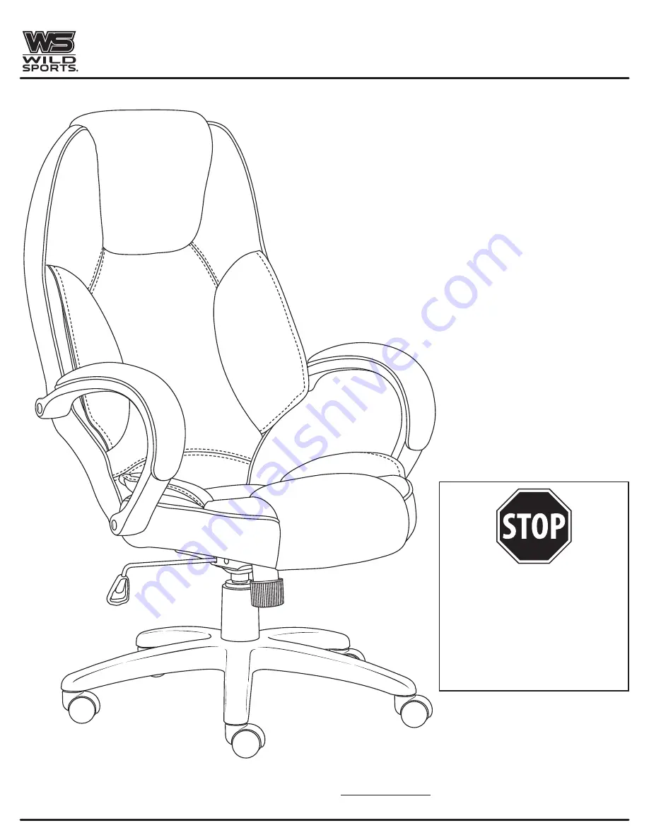
WS 5501 Series Manual Download Page 1

5501 Series

If  parts  are  missing  or  damaged, 

DO NOT return to the store.

For  immediate  assistance  with 

assembly  or  to  order  replacement 

parts, please call:

1-317-804-9160

THIS INSTRUCTION BOOKLET CONTAINS 

IMPORTANT

 SAFETY INFORMATION.  

PLEASE READ AND KEEP FOR FUTURE REFERENCE.

Summary of Contents for 5501 Series

Page 1: ... damaged DO NOT return to the store For immediate assistance with assembly or to order replacement parts please call 1 317 804 9160 THIS INSTRUCTION BOOKLET CONTAINS IMPORTANT SAFETY INFORMATION PLEASE READ AND KEEP FOR FUTURE REFERENCE ...

Page 2: ...or product defects and excludes defects caused by or arising from abuse or misuse user modification negligence or accident or if the customer fails to perform the necessary maintenance The customer is responsible for maintenance including minor assembly cleaning and lubrication and assuring that all hardware is securely fastened There are no warranties expressed or implied other than those specifi...

Page 3: ...LAT WASHER x 8 ALLEN WRENCH x 1 ARM CAP x 4 Hardware pack contains one extra of each of the machine screws and washers CASTERS x 5 5 STAR BASE x 1 TELESCOPING COVER x 1 GAS LIFT x 1 SEAT PLATE x 1 LEFT ARM x 1 RIGHT ARM x 1 BACK CUSHION x 1 SEAT CUSHION x 1 PARTS IDENTIFICATION ...

Page 4: ...e base When inserting the caster into the 5 star base apply a little pressure to the caster to pop it into position Turn the 5 star base right side up so the casters are on the floor Insert the large end of the gas lift D into the center hole in the 5 star base Place the telescoping cover C over the small end of the gas lift ...

Page 5: ... firm surface with the padded side down exposing the underside of the seat Align the holes in the seat plate E with the threaded inserts in the bottom of the seat H Insert four 1 4 20 x 11 4 machine screws 1 four lock washers 3 and four flat washers 4 through the holes in the seat plate and into the seat Tighten securely with the allen wrench 6 Hardware used in Step 2 ...

Page 6: ...til all machine screws are installed Align the holes in the support plate attached to the back cushion I over the matching threaded inserts in the seat cushion H Insert and loosely tighten a 1 4 20 x 11 4 machine screw 1 a lock washer 3 and a flat washer 4 through each of the four holes in the support plate and into the threaded inserts in the seat cushion Hardware used in Step 3 ...

Page 7: ...nto the threaded insert in the seat cushion H Tighten securely with the allen wrench 6 Repeat for the right arm G Securely tighten the 1 4 20 x 11 4 machine screws 1 installed in STEP 3 with the allen wrench 6 Insert the arm caps 5 into the screw holes in each arm Place the completely assembled seat onto the gas lift by inserting the small exposed end of the gas lift D into the hole in the seat pl...

Page 8: ...andle is released or the chair reaches the bottom position STEP 2 To Operate the Tilt Lockout Reach under the right side of the chair to find the height adjustment handle Slide PULL the lever to the right or outside direction All the way out allows the chair to rock or tilt backwards To lock the chair in the upright or vertical position sit up straight and push the lever in or to the left STEP 3 T...

Reviews: