


Special Tools
Special tools are known as specially designed tools used at particular places for assembly or disassembly of certain
components on a motorcycle. Suitable special tools are essential for complete and accurate adjusting and
assembling work. Use of special tools can realize safe, reliable and quick disassembly or assembly of components,
as well as working efficiency improvement and labor saving.
1
.
Tools used for engine overhaul
Specially designed tools are required for smooth assembly and disassembly of some components on the engine.
Special tools and pictures for engine component assembly and disassembly are listed in Table 1-1 and Table 1-2.
Table 1-1
Name Remarks
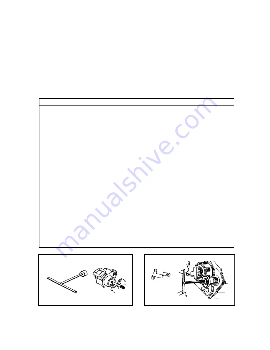
Special socket wrench
Clutch holder
Flywheel extractor
Feeler gauge
Bearing puller
Bearing installer
Oil seal remover
Puller handle
Piston pin puller
Piston ring pliers
Spark plug socket wrench
Clutch thickness measurement gauge
Cylinder bore tester
Dial gauge
Dial gauge, V-block
Micrometer
Valve guide remover
Valve guide installer
Valve clearance adjuster
Valve spring remover
Valve guide reamer
Crankcase remover
Used for disassembly/assembly of flywheel bolt, Figure 1-3
Figure 1-4
Figure 1-5
Figure 1-6
Figure 1-7
Figure 1-8
Figure 1-9
Figure 1-10
Figure 1-11
Figure 1-12
Figure 1-13
Figure 1-14
Figure 1-15
Measuring inner diameter of piston pin
,
Figure 1-16
Measuring bending of valve stem, Figure 1-17
Measuring OD of valve stem, Figure 1-18
Figure 1-19
Figure 1-20
Figure 1-21
Figure 1-22
Figure 1-23
Figure 1-24
Continued Table 1-2
Figure 1-3 Figure 1-4