


9
2.9.3
Remove the dipstick by rotating the cap
counterclockwise and pulling it out.
2.9.4
Wipe the dipstick with a clean cloth.
2.9.5
Fill the engine with oil.
2.9.6
Put the dipstick into the filler neck, then remove
it.
2.9.7
Read the oil level on the dipstick.
2.9.8
If the oil level is below the LOW or ADD mark
on the dipstick, add more oil to raise the oil level to
the FULL mark. If overfill, drain the excess oil until
the oil level on the dipstick reads FULL.
Important:
DO not overfill the crankcase with oil
and run the engine, engine damage will result.
2.9.9
Replace the dipstick into the filler neck and
rotate the cap clockwise until it is tight.
2.10 Check the Tire Pressure
Procedure
The tires are overinflated at the factory for shipping.
Reduce the pressure equally in both tires to between
12 and 15 psi (82 and 103 kPa).
2.11Check the Skids and Scraper
Procedure
Refer to Adjusting the Skids and Scraper in
Maintenance.
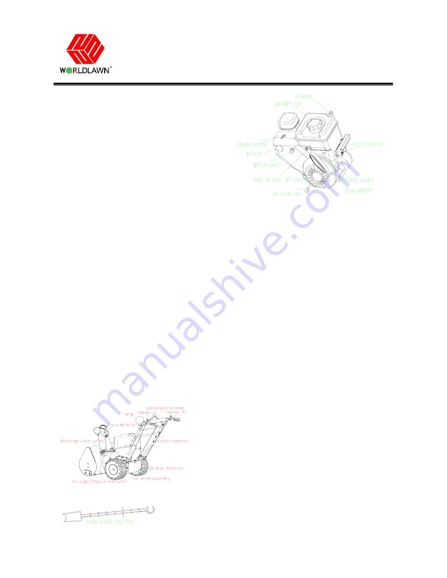
3. Product Overview
FIG
14
FIG
15
FIG 16
FIG 16 refer to engine instruction book
4
Controls
4.1 Auger/Impeller Drive Control Lever
To engage both the auger/impeller, press the lever
against the right handgrip. To disengage, release the
lever.
4.2 Traction Control Lever
To engage the traction, press the lever against the left
handgrip. To stop the traction, release the lever.
4.3 Speed Selector Lever
This control has 4 positions: 3 forward speeds and 1
reverse. To change speeds, move the speed selector
lever to the desired position. The lever locks in a
notch at each speed selection.
Note
:
Before shifting gears into or out of reverse,
you must release the traction control lever. You may
shift between any of the forward speeds without
releasing the traction control lever.
4.4 Handle-RH Locked Control
In operation process, the left side handle locks the
right side handle. Loosen the left one, the right side of
handle can be pressed or loosened freely; press the left
side handle, the right one can only be pressed, but not
be loosened.