FITTING THE DIVERTER VALVE AND CODE PLUG
6 720 645 222a (2012/05)
11
4.3
FITTING THE CODE PLUG
1. Refer to figure 14. Remove the code plug from the
controller, cut the tie securing the plug to the boiler
chassis and discard the plug and tie.
2. Fit the code plug from the kit making sure that code
plug is secured to the boiler chassis with the new tie.
B
Confirm that the number on the code plug
corresponds to the boiler type in the table above.
Fig. 14 Fitting new code plug
4.4
FITTING THE CYLINDER
TEMPERATURE SENSOR
Refer to the cylinder installation instructions for the
position of the sensor, there may already be a “sensor
pocket” available. If no “pocket” is available, for foam
insulated cylinders only with no metal jacket, follow the
steps below.
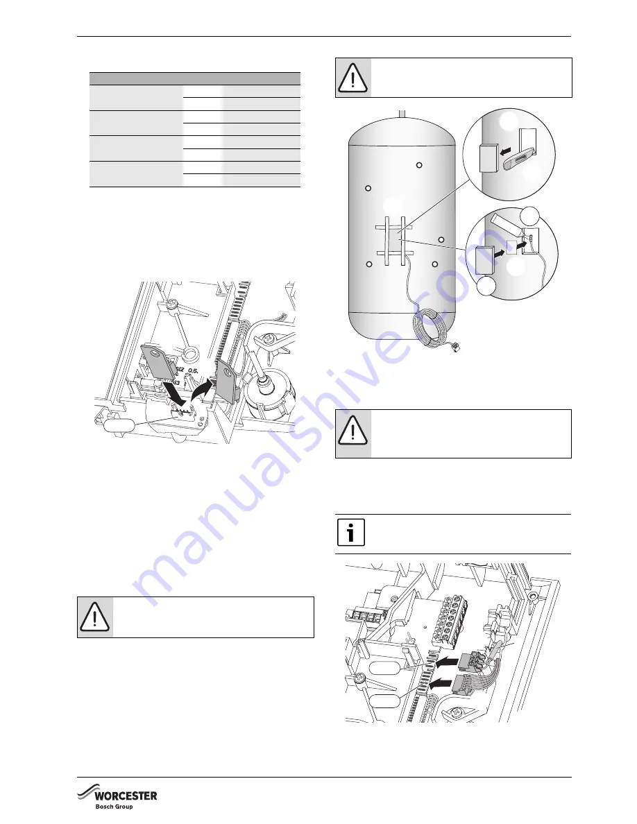
1. Mark a rectangular hole of approximately 50 by
100mm approximately one third of the cylinder length
from the bottom of the cylinder.
1. Using a sharp knife, cut through the insulation,
remove and retain the piece of insulation.
2. Apply heat conductive paste to the sensor and place
the sensor on the cylinder body in the middle of the
cut-out.
3. Hold the sensor in position with a piece of aluminium
tape.
4. Replace the insulation material.
5. Secure the insulation in place with suitable cloth
tape.
Fig. 15 Sensor connection to cylinder
4.5
DIVERTER VALVE AND SENSOR
CONNECTIONS
1. Connect the Diverter valve motor harness to the edge
connector ST17.
2. Connect the cylinder temperature sensor (1) to the
edge connector ST15.
Fig. 16 Diverter motor and sensor connections
B
Replace the control panel cover.
B
Move the control panel to the up position and secure.
Boiler size
Gas
Code plug no.
12kW i System kit
NG
1118
LPG
1119
15kW i System kit
NG
1122
LPG
1123
18kW i System kit
NG
1126
LPG
1127
24kW i System kit
NG
1114
LPG
1115
CAUTION:
Cut carefully!
B
Do not to pierce the wall of cylinder.
B
Do not cut any metal insulation jacket.
6720645222-10.1Wo
1.
2.
ST18
NOTICE:
Figure 15 applies only to foam
covered open vent cylinders.
NOTICE:
Do not route low voltage cables
alongside mains voltage cables.
This can cause interference on the low
voltage cables.
If the ST15 connector and sensor is being
used do not connect ST8 as well.
The link is not required.
6720645222-24.1Wo
6.
3.
4.
5.
2.
1.
1
6720645222-11.1Wo
1.
2.
ST15
ST17


