Installation
Greenstar 4000 – 6 720 891 162 (2020/09)
42
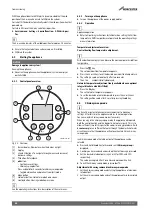
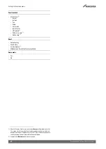
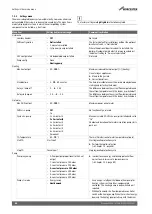
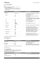
Power supply (power cables) connections
Table 19 Power supply (power cables) terminal strip for external
accessories
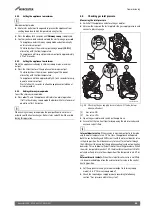
Low voltage (signal cables) terminal strip
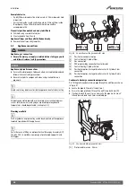
Fig. 61 Low voltage (signal cables) terminal strip
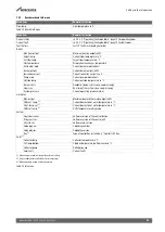
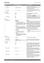
Low voltage (signal cables) connections
Table 20 Low voltage (signal cables) terminal strip for external
accessories
5.5.3
External controls - Domestic installations
External equipment or Integral diverter valve kit:
▶ External diverter valve(s) and all other 230V parts are not supplied
with the appliance.
▶ There is an optional integral diverter valve kit, this requires fitting a
diverter valve, internal pipework, cylinder sensor & connection.
See optional diverter valve kit instructions for fitting details.
This kit also allows for the Worcester controls options to be used.
▶ The power supply to external controls must be taken from the
appliance; an alternative power supply must not be used.
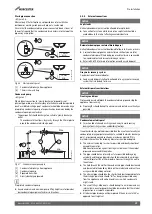
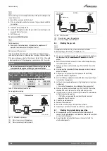
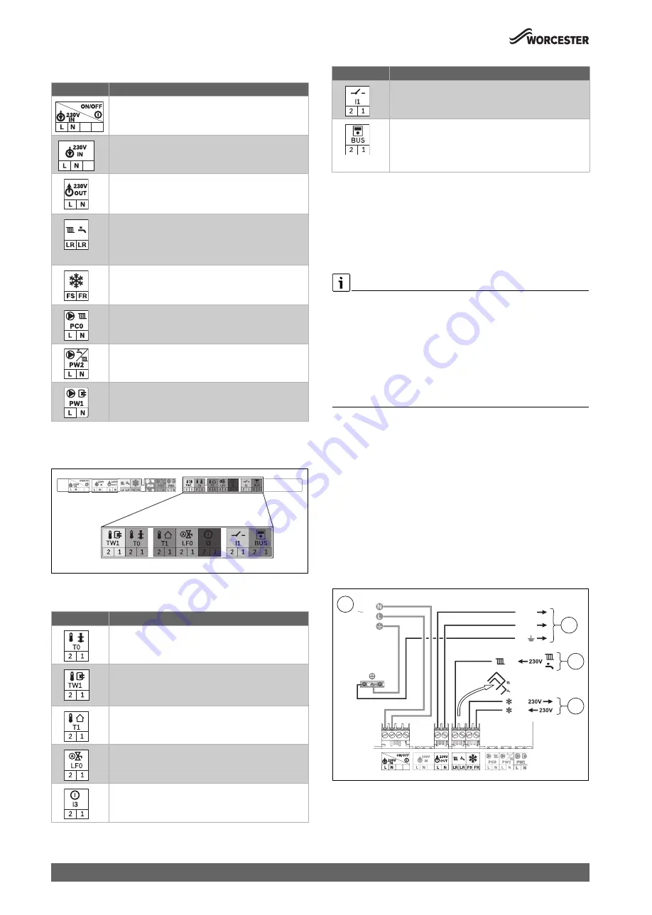
Appliance external control connections example
▶ The electrical power supply to the external equipment [2] is supplied
from 230V OUT - L (Live), N (Neutral) and PE -
\
(earth) terminals.
▶ The Switch Live from the wiring centre [3]:
– Both pre-wired links are removed, the CH & DHW demands are
combined and wired to the
(
LR terminal.
– Control for appliance Pre-heat function, optional.
The flow temperature must be set on the central heating control to
a level at least 10 °C above the required cylinder temperature set
on the cylinder control thermostat.
▶ External frost thermostat connections [4]:
– The Live supply is terminal FS
– The Switch Live is terminal FR
Fig. 62 External controls connections example
[1]
230V mains supply to the appliance.
[2]
230V supply from the appliance to the wiring centre.
[3]
CH & DHW Switch Live (Demand) from the external controls.
[4]
External frost protection Live supply and Switch Live (Demand).
Symbol
Function
Power supply (power cable).
Pre-wired cable (Live and Neutral).
No functionality; not used.
230V mains output to external controls/wiring centre.
▶ If required: connect power supply for external
controls.
Switch live (Live Return) to appliance.
•
k
CH demand input.
•
j
DHW demand input (active when optional
integral diverter valve is fitted).
External frost thermostat.
• FS output (frost thermostat supply).
• FR input (frost thermostat return).
No functionality; not used.
No functionality; not used.
No functionality; not used.
Symbol
Function
No functionality; not used.
Cylinder temperature sensor.
1)
With optional integral diverter valve fitted
▶ Connect via a 2-core cable.
Outdoor weather compensation sensor.
2)
▶ Connect via a 2-core cable.
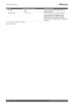
No functionality; not used.
No functionality; not used.
0010019904-002
No functionality; not used.
Communication BUS connection for hard-wired
Worcester/Bosch EMS controls.
1)
With optional integral diverter valve fitted
▶ Connect via a 2-core cable.
1) Only applicable if optional integral diverter valve is fitted
2) Diverter valve kit not required for use with Simple weather compensation
(accessory 7 716 192 764). Diverter valve kit is required for use with weather
compensation in conjunction with Worcester controls.
Symbol
Function
0010023708-001
FS
FR
LR
3
4
L
N
2
230V OUT
1
230V AC

