Installation
Greenstar 4000 – 6 720 891 162 (2020/09)
38
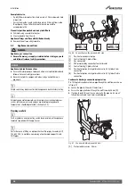
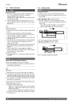
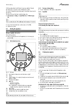
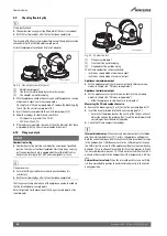
Preparing the wall frame
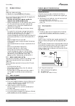
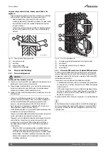
▶ Remove the temporary PRV pre-plumbing connector [3]:
– Unscrew the PRV outlet pipe [2] from the pre-plumbing
connector [3].
– Remove the screw [4] holding the pre-plumbing connector [3] in
place.
– Remove the pre-plumbing connector [3], and discard.
– Replace the screw [4] removed earlier and tighten firmly.
Removing the pre-plumbing connector [3] when the optional integral
diverter valve kit fitted.
▶ There will be an additional screw for retaining the cylinder return
connection service valve to be fitted.
▶ Fit the sealing washer for the PRV before hanging the appliance.
▶ The appliance is mounted on the wall frame utilising the central
mounting point [1], at the top of the wall frame.
Fig. 50 Wall frame preparation
Hanging the appliance
WARNING
Bonded washer (plumbing manifold gas connection)
▶ The bonded washer must be used on the gas pipe isolating valve
connection.
▶ Ensure the sealing washers are correctly seated on the appropriate
service connectors before installing the appliance.
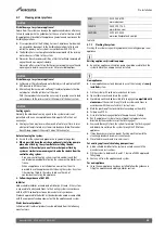
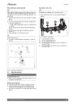
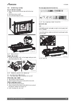
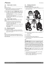
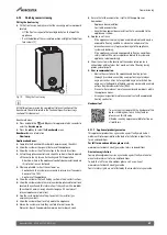
Refer to figure 51.
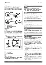
▶ Hang the appliance on to the wall mounting frame utilising the central
mounting point, at the top of the wall frame.
Fig. 51 Hanging the appliance
▶ Connect the PRV discharge pipe on the hydraulic unit onto the PRV
outlet pipework, and tighten firmly.
▶ Tighten the gas and water connections firmly.
Fitting the siphon
WARNING
Danger to life due to poisoning!
If the condensate trap is not filled, poisonous flue gas can escape.
▶ Fill the condensate trap with approximately 250 ml water before
fitting.
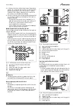
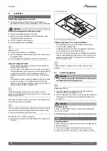
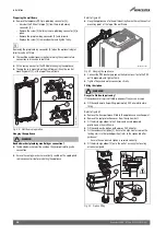
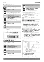
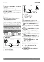
Refer to figure 52.
▶ Remove the transport piece fitted to the appliance connection point.
▶ Remove the seal protection cover from the siphon itself.
▶ Fit the discharge elbow to the 25mm condensate pipework
protrusion on the wall frame.
▶ Fill the condensate siphon with approx. 250 ml water.
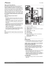
▶ Fit the condensate siphon [1]. Ensure the alignment arrow on the
locking arm is in the locked position (refer to the siphon label for
guidance).
– Ensure the condensate siphon is secured correctly.
▶ Fit the discharge elbow [2] onto the outlet, ensuring the locating
arrows are aligned.
Fig. 52 Siphon fitting
1
5
4
4
2
0010032188-001
3
0010035141-001
0010035272-001
1
2

