25
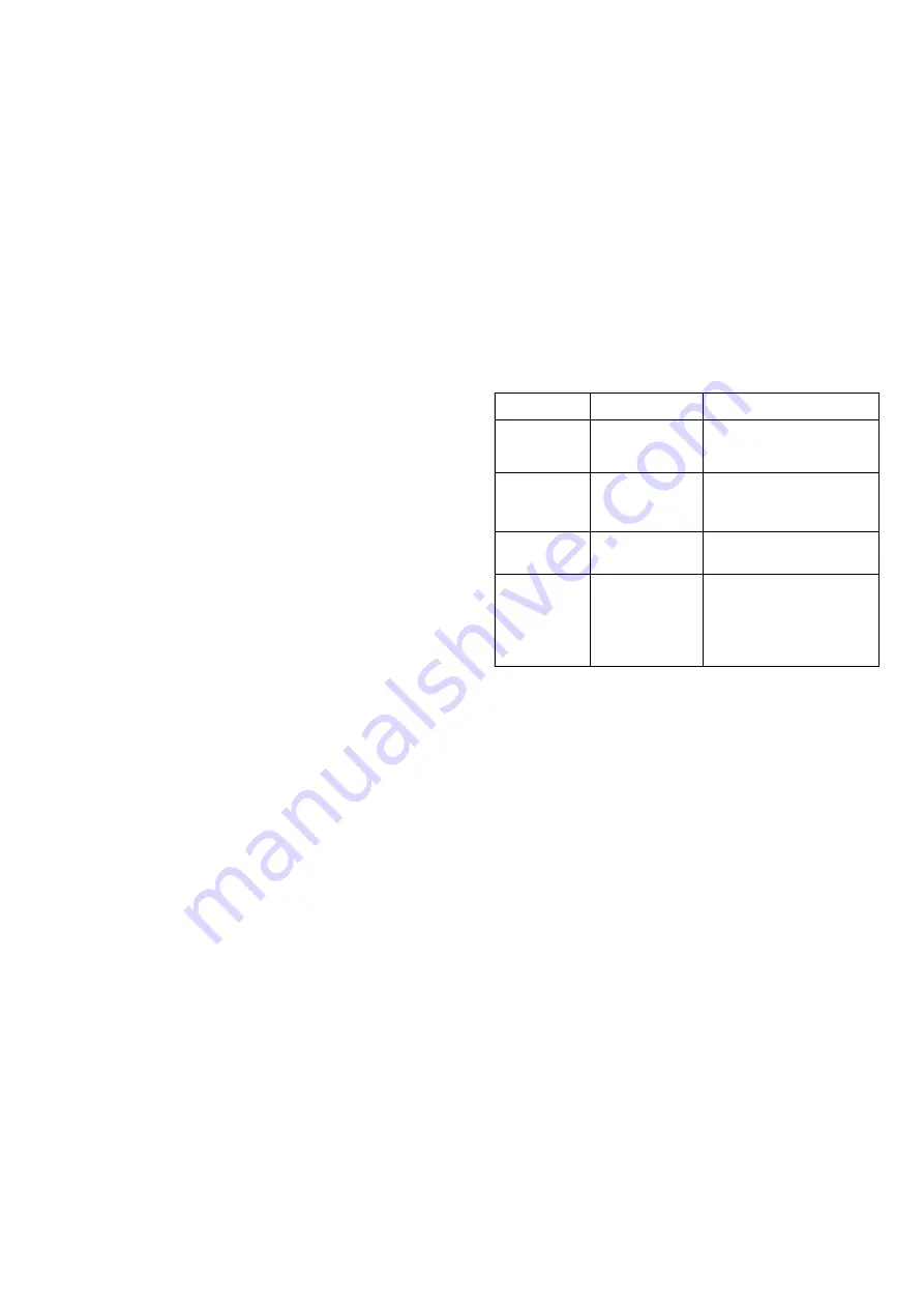
Fault Code
Frequency
Cause
Check
(Twice per second)
Limit Thermostat
operation
Check the operation of the boiler flow
temperature sensor.
Check the operation of the boiler
circulating pump.
(Once per second)
No flame detection
signal
Check flame detection circuit.
Check ignition system.
Check gas supply and gas valves
(Once every 2
seconds)
False flame detection
signal.
Inspect flame detection circuit.
Check control panel assembly.
(Once every 4
Seconds)
Air flow not detected
Check that the fan operates.
Inspect the pressure pipes from flue
outlet to Air Pressure Switch.
Check the operation of the switch
Check that the flue or air inlet ducts
are not obstructed.
The ignition transformer is located at the top RH corner of the
control.
Pull off the ignition leads from the spade terminals on the
transformer and feed each lead upwards through the grommet
in the inner casing base.
Replace in reverse order.
17.
System Pressure Gauge
Check that the electricity supply to the appliance is turned off.
Remove the front casing as detailed in section 13.3a.
Drain the central heating circuit as described in Section 14.3
(a).
Slacken the union connection on the flexible hose at the rear of
the pressure gauge. Depress the locating tabs on the gauge
body and withdraw the gauge forward from the mounting frame.
Reassemble in reverse order.
18.
Internal Fuses
Check that the electricity supply to the appliance is turned off.
Remove the front casing as detailed in section 13.3a.
Remove the control box cover by slackening the two retaining
screws and lifting clear.
The internal fuses can then be located, T2.5A on the RH side
and the T2.0A on the LH side of
the control board. Each fuse is identified on the printed circuit
board.
Remove, check and replace as required.
Reassemble in reverse order.
19.
Printed Circuit Control Board
Check that the electricity supply to the appliance is turned off.
Remove the front casing as detailed in section 13.3a.
Remove the control box cover by slackening the two retaining
screws and lifting clear.
Unplug the two multi-way plugs on the LH side of the board.
Disconnect the mains input cable from the screw terminals and
pull off the earth lead from the spade terminal and pull away the
cable locking clamp from the base. Any other external control
wiring should be removed in a similar manner.
Pull off the two edge connectors for the fan and pump supplies,
also the earth leads from the spade terminals and release the
cable clamp.
Pull off the ignition leads from the ignition transformer spade
terminals.
Slacken the two control assembly retaining screws and withdraw
the comlpete control assembly.
Remove the two retaining screws from the rear of the assembly,
ease away the metal cover by pushing upwards on the earth
terminals which protrude through to the front of the assembly.
Note:- the transformer is a plug in item on the printed circuit
board and can be removed at this point.
Gently ease away the printed circuit board from the control
housing.
Replace the items in reverse order.
20.
Pressure Relief Valve
The pressure relief valve is located at the lower RH corner of
the boiler.
Check that the electricity supply to the appliance is turned off.
Remove the front casing as detailed in section 13.3a.
Drain the central heating circuit as described in Section 14.3
(a).
Disconnect the discharge pipe from the relief valve and unscrew
the valve from the return manifold.
Replace in reverse order.
21.
Expansion Vessel
In the unlikely event of failure of the expansion vessel diaphragm
it is acceptable to leave the vessel in place and fit a replacement
(of similar capacity) external to the appliance but as close as
possibly to the CH return.
It is necessary to remove the appliance from the wall in order to
replace the expansion vessel.
Remove the expansion vessel by disconnecting the union
connection on the flexible hose at the lower edge of the
expansion vessel and withdrawing the vessel from the top of
the boiler.
Replace in reverse order.
Re-commission the appliance and CH system as described in
section 11.2.
15
Fault Finding Codes
If a problem occurs during the normal operation of the boiler
the LED wil flash and the boiler will shut down. The frequency
of the LED flashing corresponds to a fault code, as described
below. To reset the boiler controls the LED-button must be
pressed.
see also section 18 - Trouble Shooting guide
Summary of Contents for 47 311 43
Page 11: ...11 Fig 7 System filling and make up ...
Page 27: ...27 Fig 27 ...
Page 30: ...30 19 Functional Flow Diagrams ...
Page 31: ...31 ...


