22
13
Inspection and Service
13.1 SERVICING
To ensure continued efficient operation of the appliance it must
be checked and serviced as necessary at regular intervals. The
frequency of servicing will depend upon the particular installation
conditions and usage, but once per year should generally be
adequate. The extent of the service required by the appliance
is determined by the operating condition of the appliance when
tested by fully competent engineers.
Any service work must be carried out by competent engineers
such as British Gas or Corgi registered personnel.
13. 2 PRE-SERVICE INSPECTION
Check that the flue terminal and the terminal guard, (if fitted),
are clear.
If the appliance is in a compartment, check that the ventilation
openings if required in the compartment door or walls are clear.
See Section 6 - Air Supply.
Check the system and remake any joints or fittings which show
signs of leakage.
Refill, vent and re-pressurise as described in Section 11.2.
Operate the appliance and the system taking note of any faults.
Measurement of the Flue Gases
For consistency of results of the flue gas measurements it is
necessary to have a constant output and for the appliance to
be at equilibrium.
Remove the casing and switch on the appliance.
Switch to DHW and CH mode.
Turn the DHW temperature control to the Max. position.
Turn on a tap to create a hot water demand.
Wait until the appliance reaches thermal equilibrium (approx.
10 minutes).
A combustion products sampling point is provided in the pressure
sensing tube to the Air Pressure Switch, the test point being
located a the lower RH side of the boiler.
Connect the sampling probe and ensure an air tight connection.
Expected measurements should be between:
the burner into the combustion chamber and turning it over
towards the rear. The burner can then be slid forwards from the
combustion chamber. Inspect and if necessary clean the burner
blades. Remove the 8 screws securing the burner manifold.
Inspect and if necessary clean the injectors.
Do not use a metal probe or brush.
(d) Heat exchanger
Remove the fan and burner assembly as described above.
Remove the two top panel retaining screws and slide off the top
cover plate. Cover the gas supply to burner orifice. Inspect the
finned copper heat exchanger and clean as necessary using a
soft brush. Re-assemble the appliance in the reverse order.
13.5 TEST THE APPLIANCE
On completion of the service and reassembly of the appliance,
check for gas soundness and the correct operation of the
appliance as described in Section 11 - Commissioning.
Refit the cabinet front panel and reset the controls to the users
requirements.
13.6 Inlet water filter
Remove the water flow regulating valve as described in section
6.
Pull out the retaining clip from the valve body and withdraw the
brass housing and filter.
Clean or replace the filter as required.
Reassemble in the reverse order.
After taking the measurements ensure that the sample point is
resealed.
IMPORTANT
Disconnect the electrical supply at the mains and turn off the
gas supply at the gas service cock on the appliance before
servicing.
After completing the service always test for gas soundness as
indicated in BS 6891.
13.3 DISMANTLE THE APPLIANCE
To carry out a full and comprehensive service of the appliance
remove the following parts to gain access to the components
which need to be checked or serviced. Check that the gas and
electricity supply to the panel is turned off.
(a) Cabinet Front Casing.
Remove outer casing by unscrewing the 2 lower retaining screws
and lifting vertically upwards.
(b) Fan
Remove the fan by unscrewing the 2 front fixing screws,
disconnect the electrical connections and rotate the fan slightly
to the left. Inspect and if necessary clean the fan impellor.
(c) Burner
Remove the burner by unscrewing central union nut, lift slightly
at the front, disconnect the electrode connections, remove the
burner by first turning it upside down by raising the front edge of
CO%
CO
2
%
Natural Gas
0.001 to 0.01
6.5 to 7.0
Propane
0.001 to 0.01
7.6 to 8.2
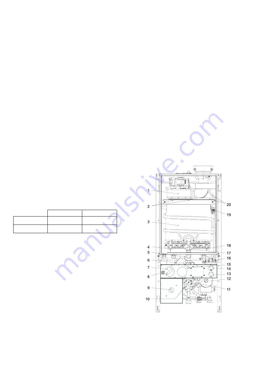
11 Water valve
12 Pump
13 System temperature
indicator
14 System pressure gauge
15 Gas pressure setting
screw
16 Air pressure switch
17 Burner fixing nut
18 Flame sense electrode
19 High limit thermostat
20 Air pressure sensing tubes
1 Fan
2 Fan fixing screws
3 Heat exchanger
4 Ignition electrode
5 Burner pressure test point
6 Gas valve
7 CH temperature control
knob
8 Reset button
9 Mains electricity switch
10 DHW flow rate /
temperature selector knob
Table 10
Summary of Contents for 47 311 43
Page 11: ...11 Fig 7 System filling and make up ...
Page 27: ...27 Fig 27 ...
Page 30: ...30 19 Functional Flow Diagrams ...
Page 31: ...31 ...


