17
5) Finishing the flue.
Apply the plastic tape provided to the last section of flue where
it will be sealed to the external brickwork.
Remove the front clamp from the boiler flue connection and
lower the flue duct sleeve by slackening the single locking screw
at the RH side of the internal flue duct (fig. 14).
Fit the turret complete with boiler adapter to the flue system.
From inside, push the assembly through the wall, align the flue
turret with the boiler flue connection. For side flues the turret
will need to be twisted into place through 90° to locate into the
boiler flue connection. Replace the clamp and raise the inner
flue connection and lock into place (fig. 14).
Make good the intenal and external brickwork or rendering.
6) Fitting the restrictor ring
Refer to table 5 to select the correct restrictor ring depending
on the equivalent length of the flue system.
Remove the fan, as described in replacement of parts. Remove
the three screws holding the fan to its mounting plate and position
the appropriate restrictor in the recess on the fan mounting,
plate and refit the three screws securing the restrictor, mounting
plate and fan. Replace the fan on the boiler.
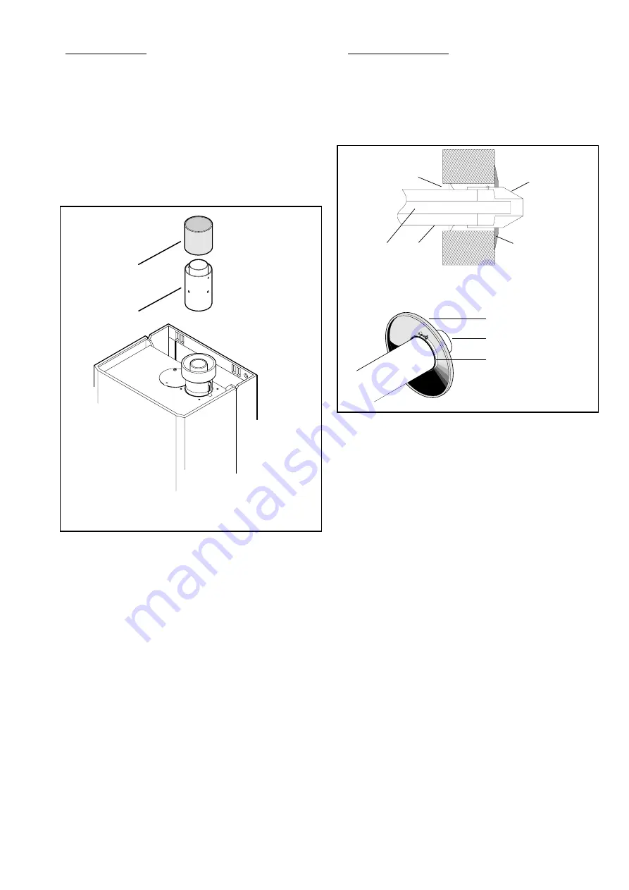
10.5 INTERNAL FITTING OF THE DUCT ASSEMBLY
The rubber sealing gasket and the clamping ring are available
from Worcester Heat Systems. Measure and cut the ducts as
previously described for external fitting (Section 10.4). Fix the
ducts to the terminal and fit the rubber sealing gasket and clamp
to the terminal. Centralise the gasket and tighten the clamping
ring. See Fig. 21. Slide the flue centering ring onto the air duct
and tighten the screw. See Fig. 22. Fix the ducts and terminal
assembly to the flue turret and boiler as described in Section
10.4 preceding, together with the appropriate restrictor ring.
Apply the plastic tape provided to the last section of the flue
where it will be sealed to the external brickwork. Push the
assembly through the wall so that the gasket flange is against
the outside of the wall. See Fig. 22. Align the flue turret and
adapter with the socket on the appliance, slide or twist the turret
into the boiler flue connection as described in section 10.4
preceding together with the appropriate restrictor ring.
1 - Adapter, boiler to turret
2 - Adapter, item 1 to vertical flue
Rubber sealing gasket
Flue terminal
Clamping ring
1. Flue centering ring
2. Air duct
3. Flue duct
1
3
2
4
5
4. Rubber sealing gasket
5. Flue terminal
10.6 FLUE BENDS
See Figs. 22 and 23.
Measure distances X, Y and Z as appropriate.
RH Side flue duct length = X + 70 mm. See Fig. 22.
LH Side flue duct length = X + 250 mm.
Rear flue duct length = X + 155 mm. See Fig.22.
Cut the flue and air ducts which are to make up the first section
X such that both the assemblies are of equal length (either X +
70 mm, X + 250 mm or X + 155 mm). Extensions will be
necessary to allow X to be larger than 250 mm. Any extension
ducts are fixed by drilling a pilot hole through the hole in the
duct or elbow and screwing the self tapping screw provided into
the two ducts. (See Fig.22). The length Y is the distance between
bends the ducts must be cut to Y - 162 mm. The swaged ends
must be removed from the extension tube and only the air duct
needs fixing. See Fig.22. Z is the final flue length from the last
elbow to the outside face of the external wall. The first duct
sections fitted to the elbow must have unswaged ends. The
length of the air ducts should be Z - 196 mm. The inner flue duct
must be 30 mm longer than the air duct. If Z - 196 mm is less
than 160 mm then the terminal section will need to be shortened
to the same length as the extension flue section fitted to the
elbow (length Z - 100). If flue extensions are needed to attain
the required length care must be taken to ensure that the last
section of flue is longer than 260 mm.
Each extension must be connected to the previous section of
flue or bend by firstly fitting the inner flue ducts togther and pilot
drilling and fixing as above (See Fig. 22). Then the outer air
ducts can be similarly fixed using a pair of screws provided.
The flue terminal section can then be telescopically adjusted
and fixed as before (See Fig. 22), ensuring the correct length of
Z - 41. The silicon sealant supplied should be applied to the
flue ducts which engage into elbows. See Fig. 22.
Fig. 20
Fig. 21
1
2
Summary of Contents for 47 311 43
Page 11: ...11 Fig 7 System filling and make up ...
Page 27: ...27 Fig 27 ...
Page 30: ...30 19 Functional Flow Diagrams ...
Page 31: ...31 ...


