Remove the cabinet front panel.
Check that the electrical supply and the gas service to the
appliance are off. See fig 3.
Check that all the water connections throughout the system are
tight.
Open the system valves at the appliance. See fig 3.
Open all the radiator valves, fill the system and vent each
radiator in turn.
The automatic air vent (fixed to the flow manifold) will vent the
appliance. Check that the air vent cap has been loosened.
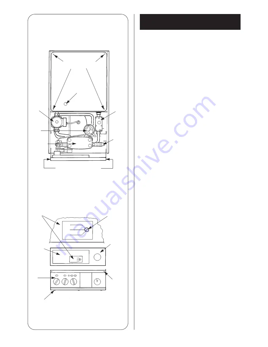
see fig. 20.
Check that the pressure relief valve operates by turning the knob
ant-clockwise until it releases. Water should be expelled from the
discharge pipe. see fig. 28.
Lower the control box to gain access. Refer to Section 13.3(c).
Sealed systems only.
Set the Expansion Vessel Pressure.
The charge pressure of the expansion vessel as dispatched is
0.5 bar, which is equivalent to a static head of 5 meters (17ft).
The charge pressure must not be less than the static head at the
point of connection. See fig. 5. A Schraeder type valve is fitted to
the expansion vessel to allow the charge pressure to be
increased if necessary.
Set the System Pressure.
To fill the system, insert the bayonet end of the filling key into the
corresponding cut-outs in the filling loop housing and twist to
lock the key in place. See fig. 6.
Turn the system filling knob anti-clockwise to allow water ingress
and fill until the pressure gauge is at 2.5 bar (37 lb/in
2
).
Turn the knob cockwise to stop filling and remove the filling key
by lining up the bayonet end of the key with the cut-outs in the
filling loop housing and withdrawing the key. (See fig. 7.)
Check for water soundness.
Release water from the system using the relief valve test knob
(see fig. 28.), until the initial system design pressure is obtained,
up to a maximum of 1.5 bar.
Intial system design pressure (bar)=
Expansion vessel charge pr 0.3 (bar).
Note:
1 bar is equivalent to 10.2 meters (33.5 ft) of water.
N.B. The key must always be removed from the filling loop
housing after the system has been filled to comply with
Bylaw 14 of the Water Byelaws Scheme and to prevent
accidential filling.
Store the key in a safe place for future use.
Set the movable pointer on the pressure gauge to coincide with
the indicating pointer giving a permanent record of the set
system pressure.
If the pressure indicated on the pressure gauge is greater than
2.6 bar when operating at the maximum central heating
temperature, an extra expansion vessel must be fitted to the
system as close as possible to the appliance central heating
return connection.
The appliance (as despatched) can accommodate a system
volume of 83 litres. Refer to BS 7074 Part 1. If the system volume
is in excess of that accommodated by the expansion vessel fitted
to the appliance then an extra vessel must be fitted as close as
possible to the central heating return connection of the
appliance.
Any extra vessel fitted must be pressurised to the same figure as
the integral vessel. If the expansion vessel fails then the specified
replacement must be fitted.
20
11.1. Appliance and central heating
system preperation
Fig. 27. Appliance Casing, Facia Controls and
Location of Equipment.
Inner casing cover
fixing screws (4)
Burner
observation
hole
Circulating
pump
Air
pressure
switch
Water to
water heat
exchanger
Gas
valve
Pressure
relief
valve
Facia shown in the service
position
Detail of gas valve
mode switch
MIN
MAX
NORMAL
Screwdriver slot
adjustment
Plastic
water cover
over controls
and gas
mode
switch
Rear of
facia
shown in
service
position
Facia
panel
fixing
screws
(2)
Front of
facia
panel
Bottom facia fixing
screws (3)
Summary of Contents for 26CDi Xtra
Page 35: ...35 96 NG OR LPG NG OR LPG 109 201 ...
Page 47: ...47 ...


