Manual 37441C
DTSC-50 - ATS Controller
Page 8/106
© Woodward
Overview
≡≡≡≡≡≡≡≡≡≡≡≡≡≡≡≡≡≡≡≡≡≡≡≡≡
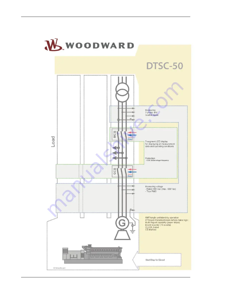
Figure 1-2: Functional overview
Page 1: ...37441C Manual Software Version 1 00xx or higher Manual 37441C DTSC 50 ATS Controller...
Page 2: ...off before disconnecting the battery from the system Electronic controls contain static sensitive parts Observe the following precautions to prevent dam age to these parts Discharge body static befor...
Page 3: ...ious software version 1 0003 New features Modbus protocol was implemented Content CHAPTER 1 GENERAL INFORMATION 7 Related Documents 7 Overview 8 CHAPTER 2 DTSC 50 OVERVIEW 10 CHAPTER 3 ELECTROSTATIC D...
Page 4: ...e Delay Time 48 CHAPTER 9 CONFIGURATION 49 Restoring Default Values 49 Resetting Via the Front Panel 49 Resetting Via LeoPC1 49 Configuration Via the Front Panel 49 Configuration Using the PC 50 Editi...
Page 5: ...ATA 86 CHAPTER 14 ACCURACY 88 APPENDIX A COMMON 89 Alarm Classes 89 Conversion Factors and Charts 90 Conversion Factors Temperature 90 Conversion Factors Pressure 90 Conversion Chart Wire Size 90 APPE...
Page 6: ...display 27 Figure 7 2 6 digit 7 segment LED display 29 Figure 10 1 Voltage frequency hysteresis 64 Figure 11 1 Modbus visualization configurations 78 Figure 12 1 GetEventLog interface configuration 84...
Page 7: ...arameter visualization remote control data logging language upload alarm and user management and event recorder management This manual describes the use of LeoPC1 software LeoPC1 Engineering Manual 37...
Page 8: ...Manual 37441C DTSC 50 ATS Controller Page 8 106 Woodward Overview Figure 1 2 Functional overview...
Page 9: ...ed as described in this manual The prerequisite for a proper and safe operation of the product is correct transportation storage and installation as well as careful operation and maintenance NOTE This...
Page 10: ...e DPC is not part of the DTSC 50 shipment and sold separately P N 5417 557 IMPORTANT NOTE ABOUT COUNTERS The counters for Operation hours Maintenance Interval Number of starts can be recalibrated with...
Page 11: ...c bottles and plastic ash trays away from the control the modules and the work area as much as possible 4 Opening the control cover may void the unit warranty Do not remove the Printed Circuit Board P...
Page 12: ...el Cut Out 40 136 158 136 158 Figure 4 1 Housing panel cut out Description Dimension Tolerance Height Total 158 mm Panel cut out 138 mm 1 0 mm Housing dimension 136 mm Width Total 158 mm Panel cut out...
Page 13: ...panel cut out is not big enough enlarge it accordingly Ensure that the gasket is placed properly if used Ensure that the paper strip is not pinched between gasket and panel to maintain isolation 5 At...
Page 14: ...free configurable Discrete input DI 05 isolated Reply GCB free configurable Common terminals 15 to 20 DI 01 DI 02 DI 03 DI 04 DI 05 Subject to technical modifications DTSC 50 DTSC 50 Wiring Diagram R...
Page 15: ...in the following chapter are indicated in square millimeters Please refer to Conversion Chart Wire Size on page 90 to convert the sizes to AWG Terminal Arrangement 2019 1 2 2122 40 39 3536 upper term...
Page 16: ...er operation of the device a minimum initial voltage of 10 5 Vdc is necessary when switching on the DTSC After this a continuous operating voltage between 6 5 and 32 Vdc is possible to operate the DTS...
Page 17: ...asurement display and protection are ad justed according to the rules for delta connected systems Monitoring refers to the fol lowing voltages VL12 VL23 VL31 1Ph 2W Measurement is performed for single...
Page 18: ...N Generator voltage3Ph4W G Figure 6 3 Voltage measuring generator 3Ph 4W Voltage Measuring Generator 3Ph 3W G L1 L2 L3 GCB 29 31 33 35 L3 L2 L1 N Generator voltage3Ph3W Figure 6 4 Voltage measuring g...
Page 19: ...nd the Generator rated voltage Parameter 11 must be configured to the phase phase voltage 33 35 L1 N Generator voltage1Ph2W 31 29 L3 L2 L1 L2 GCB G Figure 6 7 Voltage measuring generator 1Ph 2W phase...
Page 20: ...1 N Mainsvoltage3Ph4W MCB L1 L2 L3 N Figure 6 8 Voltage measuring mains 3Ph 4W Voltage Measuring Mains 3Ph 3W 21 23 25 27 L3 L2 L1 N Mainsvoltage3Ph3W MCB L1 L2 L3 Figure 6 9 Voltage measuring mains 3...