38
Assembly
MAN1281 (4/15/2019)
4.
Attach stationary blade (5) to mounting bracket
using two cap screws (10), four hardened flat
washers (15) and lock nuts (11).
NOTE:
Stationary blade should fit between the two
rotating blades on the crossbar.
5.
Replace skid shoe using existing hardware if
removed.
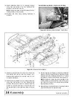
Install Stationary Blades - Right and Left Wing
Figure 29
. Stationary Blade Installed - Right Wing
Figure 30
. Shredder Kit Installation
1.
Attach mounting bracket (6) to the front side of the
front baffle and secure with cap screws (12),
hardened flat washers (14) and lock nuts (13). Do
not tighten hardware.
2.
Attach stationary blade (5) to mounting bracket (6)
using two cap screws (10), four hardened flat
washers 915) and lock nuts (11). Blade should be
angled by using the first hole on the left side and
the second hole on the right side. Refer to Figure
29.
3.
Rotate crossbar and blades so stationary blade fits
between the two crossbar blades. Adjust mounting
bracket (6) so the stationary blade (5) is 1" below
flat blade (4), Tighten all hardware. See Figure 29.
NOTE:
Stationary blade should be parallel to the
rotating blades, point toward the center of the gear-
box and rear of cutter, and overlap rotating blades
approximately 4 inches.
4.
Repeat steps to install stationary mounting bracket
(6) and blade (5) to the opposite wing.
5
15
10
13
14
12 14
Summary of Contents for BATWING BW13.70
Page 55: ...Common Components 55 MAN1281 4 15 2019 NOTES...
Page 56: ...56 50 Series Parts MAN1281 4 15 2019 CENTER FRAME ASSEMBLY BW20 50 BW20 50Q...
Page 60: ...60 50 Series Parts MAN1281 4 15 2019 WING CENTER GEARBOX ASSEMBLY BW20 50 BW20 50Q...
Page 65: ...50 Series Parts 65 MAN1281 4 15 2019 NOTES...
Page 66: ...66 60 Series Parts MAN1281 4 15 2019 CENTER FRAME ASSEMBLY BW20 60 BW20 60Q...
Page 70: ...70 60 Series Parts MAN1281 4 15 2019 WING CENTER GEARBOX ASSEMBLY BW20 60 BW20 60Q...


