


18
Operation
MAN1281 (4/15/2019)
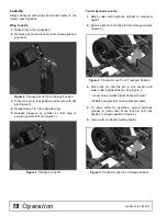
Lock-Up
Always transport with wings and center frame in the
raised, locked position.
Wing Lock-Up
1.
Raise wing to the up position.
2.
Remove klik pin and lock pin from storage position
(Figure 2).
Figure 2
. Transport Lock Pin in Storage Position
3.
Place lock pin in lock position and secure with klik
pin (Figure 3).
4.
Repeat steps 1 to 3 for opposite wing.
5.
Release pressure on cylinder so that wing is
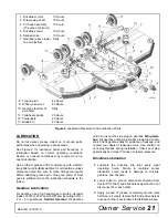
secured against lock pin (Figure 3).
Figure 3
. Transport Lock Pin
Center Section Lock-Up
1.
Raise cutter with hydraulic cylinder to maximum
height.
2.
Remove klik pin and lock pin from storage position
(Figure 5).
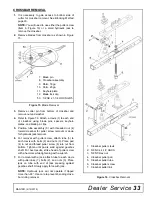
Figure 4
. Transport Lock Pin In Transport Position
3.
Place lock pin and klik pin in lock position and
lower cutter against lock pin. See Figure 4.
• Upper hole provides higher transport height.
• Middle hole provides narrow transport width.
4.
To lower cutter for operation, extend hydraulic
cylinder to raise cutter. Move lock pin from lock
position to storage position (Figure 5).
5.
Lower cutter to desired cutting height.
Figure 5
. Transport Lock Pin In Storage Position
Summary of Contents for BATWING BW13.70
Page 55: ...Common Components 55 MAN1281 4 15 2019 NOTES...
Page 56: ...56 50 Series Parts MAN1281 4 15 2019 CENTER FRAME ASSEMBLY BW20 50 BW20 50Q...
Page 60: ...60 50 Series Parts MAN1281 4 15 2019 WING CENTER GEARBOX ASSEMBLY BW20 50 BW20 50Q...
Page 65: ...50 Series Parts 65 MAN1281 4 15 2019 NOTES...
Page 66: ...66 60 Series Parts MAN1281 4 15 2019 CENTER FRAME ASSEMBLY BW20 60 BW20 60Q...
Page 70: ...70 60 Series Parts MAN1281 4 15 2019 WING CENTER GEARBOX ASSEMBLY BW20 60 BW20 60Q...


