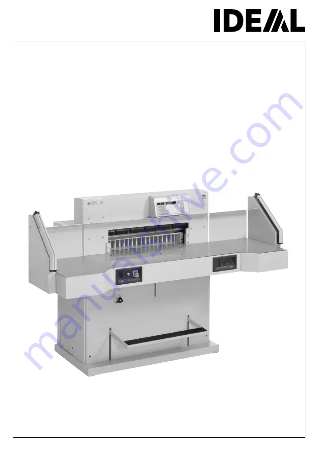
IDEAL 7228-06 LT
GB Operating Instructions
Guillotines
Page 1: ...IDEAL 7228 06 LT GB Operating Instructions Guillotines...
Page 2: ...ento esta m quina y cumpla las normas de seguridad Las instrucciones de servicio y seguridad deben estar siempre disponibles S L s igenom denna bruksanvisning innan ni startar maskinen Var noga med s...
Page 3: ...PL Dzieciom nie wolno obs ugiwa urz dzenia RUS H Gyerekek a g pet nem kezelhetik TR Makinay ocuklar Kullanmamal d r DK M kun betjenes af voksne CZ Stroj nesm b t obsluhov n d tmi P As crian as n o de...
Page 4: ...Non lasciare mai la lama incustodita Non rimuovere o trasportare la lama senza protezione Vedi pagina 29 e 31 Attenzione Rischio di infortunio E No quitar la cuchilla sin prestar atenci n No desmontar...
Page 5: ...terlades uden opsyn Fors g ikke at afmontere eller transportere knivbladet uden beskyttelse Se side 29 og 31 FARE Risiko for legemlig beskadigelse CZ Nikdy nenech vejte n bez krytu Nikdy nevyj mejte n...
Page 6: ...gliacarte esclusivamente per il taglio di risme di carta o materiali analoghi E No cortar materiales duros o materiales que puedan astillarse S F rst r inte h rt material eller material som kan splitt...
Page 7: ...nstructed for one man operation only Warning Clips or similar damage the cutting blade Disconnect from the mains before starting any service work or before removing the panels Replacement of blade and...
Page 8: ...operator is protected by a two handed control system C and safety beam guard D All components which may endanger the operator are covered by a guard A Do not operate the machine without the following...
Page 9: ...witch apressed Is the black overload switch bpressed Check on site fuse If the machine still does not function then the rotation must be reversed The machine is wired according to the IEC standards We...
Page 10: ...10 IDEAL 7228 06 LT When not in use for a longer period switch off Main switch to 0 Safety precautions Ensure free access to mains...
Page 11: ...accessories Attach the side tables to the front table so that the upper surface is level Screws and nuts are in a plastic bag in the tool set B Reassemble the safety light beam For transport through n...
Page 12: ...12 IDEAL 7228 06 LT Plug into socket Installation...
Page 13: ...e functioning and complete before use All covers have to be mounted A Safety beam guard must be mounted B The release for cutting is allowed only if the two hand safety device is operated at the same...
Page 14: ...to the right B Press Sbutton D machine will automatically go to 72 cm or 28 346 inches The machine is now ready for use Operation The measurement is set as follows manually with the electric hand whee...
Page 15: ...be used as cutting line indicator for cutting Pre clamping can be performed using the foot pedal D Only use the optical cutting line indicator and mechanical cutting line indicator when no exact cut i...
Page 16: ...provided holder C LED Vdeletes The remaining cut without false clamp is 20 mm Warning Make sure the false clamp is in the provided holder otherwise the measurement from 20 mm 89 mm cannot be cut To mo...
Page 17: ...the front table Cutting activation Press both buttons of the two handed control system A simultaneously and keep them pressed until the paper is completely cut The safety area B must be free To interr...
Page 18: ...ment H Foot pedal I Airtable switch J Program number K Program step L LED M display memory M LED E display eject N LED S display error indication O Display cutting size cm or inch P Backgauge backward...
Page 19: ...ied dimensions Enter dimension on the numerical key pad W LED S N appears Press S button dimension is approached LED S disappears Insert paper and move by means of the paper knock up block to the back...
Page 20: ...tton A on the display K Enter the multiple cut size Press S button backgauge will advance by the multiple cut size After cutting the backgauge will advance by the multiple cut size Pressing the s butt...
Page 21: ...he button b and j Program on display J program number Step on display K program step The indicated program step can be overwritten at any time These programs remain stored when the machine is off Shou...
Page 22: ...program step appears Enter the next dimension gStore the dimension p s Escape the program mode Eject function program The eject function can be added each time a measurement is entered and ejects befo...
Page 23: ...position 50 cm Insert paper Release cut 1 Release cut 2 cuts multiple size 2 cm Release cut 3 cuts multiple size 2 cm Backgauge proceeds to position 50 cm ps escape the program mode Changing select pr...
Page 24: ...Basic setting 21 cm 8 267 x Basic setting 14 85 cm 5 846 y Basic setting 10 50 cm 4 133 z Eject Basic setting 20 cm 7 87 Changing a basic setting Press pand hold press w Setting blinks Enter new sett...
Page 25: ...r knock up block b to the backgauge Iand side lay on the left J Release the cut after every cut the backgauge advances to the next position With the button rand h you are able to change between severa...
Page 26: ...f the blade height is less than 83 mm 3 29 inches A new blade must be used The blade may only be ground by a qualified supplier or from the manufacturer Krug Priester D 72336 Balingen Danger Risk of i...
Page 27: ...ment A to the top until it stops Spanner found in tool set C Remove spanner Danger Risk of injury Lower the blade by pressing both cutting buttons 1 Keep one button pressed and turn off the main switc...
Page 28: ...counter clockwise to position 0 with the special wrench and attachable extension pipe A in the tool set The slot must correspond to position 0 B Remove the special wrench and turn on the main switch u...
Page 29: ...t the blade changing tool A into place and fasten it to the blade 3 Remove 4 blade screws 1 Loosen the grips 2 of the blade changing tool A lightly and allow the blade to be taken downwards out of the...
Page 30: ...e the cutting stick according to top picture Turn the cutting stick the non used side must be near to the blade and plug it into the left holding bolt Danger Risk of injury Cutting test after replacin...
Page 31: ...e changing tool A Make sure there is a space ot 10 mm or 0 39 inches B Blade must be covered C Danger Risk of injury Place the blade to be exchanged with the blade changing tool A mounted 1 into the b...
Page 32: ...ade screws with washers 1 Remove the blade changing tool A 2 Lightly tighten the remaining blade screws with washers 3 Remove all tools and distribute paper along the entire cutting length 1 Turn main...
Page 33: ...button pressed and turn off the main switch 2 Blade and cutting stick replacement With the special wrench A the 3 eccentrics should be screwed down until the paper is cut along the entire length of th...
Page 34: ...tely cut gradually turn the blade depth adjustment A 1 12 downwards until all the paper is completely cut Do not set too low as blade will become blunt sooner Blade and cutting stick replacement Turn...
Page 35: ...un Advance the backgauge as far as possible to the front Use non resinous oil or grease Maintenance and cleaning Danger Maintenance work may only be performed by trained staff Disconnect the mains bef...
Page 36: ...he remaining parts twice a year see picture The main switch must be on 0 B Disconnect from the mains Remove the front upper housing E taking care of the cable Remove lower panel and rear wooden panel...
Page 37: ...es not function Is the machine plugged in Main switch to position I A Control system activated B Turn key to the right Check the units fuse and the on site circuit breaker Release a cut see page 17 Po...
Page 38: ...be made in the socket It is also possible to make alterations in the plug by exchanging L1 and L2 Danger Incorrect exchanging of the connections will endanger the operator This work must be carried ou...
Page 39: ...Reset the safety button A Machine blocked Blade is blunt Eliminate the cause and push the safety button A Backgauge blocked Safety button B ejects Eliminate the cause and push the safety button B Saf...
Page 40: ...hrough the last sheet Turn or turn around the cutting stick A readjust the blade by means of blade depth adjustment B see page 34 Poor cutting quality or blade stays in the paper stack Change the blad...
Page 41: ...activated Inform the Service Team www ideal de Service service krug priester com Display illumination off Is the machine plugged in A Is the main switch on position I B Push in the green safety butto...
Page 42: ...c oil needs refilling Contact your dealer Sender Receiver Trouble shooting light beam During normal operation the LED A must iluminate orange and LED B green Display C is permanently on orange when th...
Page 43: ...43 None of the above mentioned methods helped to solve the problem Contact Service Team under www ideal de Service service krug priester com Possible malfuntions...
Page 44: ...commended accessories HSS Blade Nr 9000 141 Cutting stick 6 pieces Nr 9000 039 Blade changing tool 1 Nr 9000 514 Paper knock up block 1 Nr 9000 521 Side tables left and right Nr 9000 550 1 Included in...
Page 45: ...to DIN 51562 Used oil must be disposed of at the authorised place 1 with side tables The exact technical specifications can be found on the technical specifications sticker A on the machine A wiring d...
Page 46: ...d by independent safety laboratories and is in compliance with the EC regulations 98 37 EG 2006 95 EG and 2004 108 EG Sound level information The sound level is 72 db A as defined by EN 13023 Subject...
Page 47: ...ions pertinentes suivantes voldoet aan de eisen van de in het vervolg genoemde bepalingen conforme alle seguenti disposizioni pertinenti satisface las disposiciones pertinentes siguientes 98 37EG 2006...
Page 48: ...IDEAL Made in Germany IDEAL Krug Priester 72336 Balingen Germany www ideal de Document Shredders Trimmers and Guillotines Printed in Germany IDEAL 05 2006...