10
Adjusting the movable cutter,
No. 3 with press rolls.
Set the cutter head from side to side.
(Work piece dimension)
Loosen the locking handle item 91
attached to slide under the table or
track and screw that sits above the
spool pos 74 Then set the cutter with
the crank pos 260 on the side of the
plane to the desired cut width. One
revolution of the crank is 4 mm.
The indicator
The indicator shows the width
dimension in mm, black, and 1 / 10
mm, red. At each shift to the new
profile: planing a board, measure the
outer dimension of caliper,
Turn the small knob on the right
indicator so this measurement is
shown in the window. Then set the
correct dimensions.
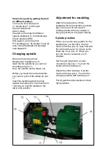
Adjust the arm pos 77 with side rollers
so that the board will be printed in
police custody.
Set up roller item 76 so that it extends
1-2 mm from the minimum flight
diameter cutter.
Press roller height can be changed
with
washers under or over it. Needed in
some cases when profiling.
Summary of Contents for PH365
Page 18: ...18 Overview ...
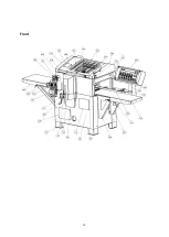
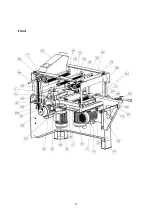
Page 19: ...19 Front ...
Page 20: ...20 Front ...
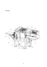
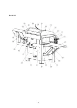
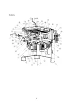
Page 21: ...21 Backside ...
Page 22: ...22 Backside ...
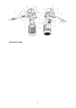
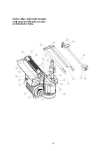
Page 23: ...23 Left vertical cutter ...
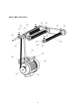
Page 25: ...25 Upper cutter feed rollers ...


