background image

Sharpener Operator’s Manual

3. CALIBRATING THE ADVANCEMENT

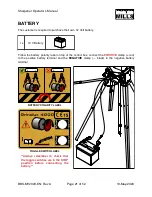
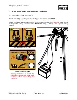
A. CONNECT THE BATTERY 

Before connecting the battery ensure both toggle switches are set to 

STOP

.

Follow the battery polarity label on top of the control box: connect the 

POSITIVE

 clamp (+ red) 

to  the  positive  battery  terminal  and  the 

NEGATIVE

  clamp  (—  black)  to  the  negative  battery 

terminal.

BBS-MY2020-EN: Rev A

Page 

 of 

30

52

19-May-2020

**Always  remember  to  check  that 
the toggle switches are in the STOP 
position  before  connecting  the 
battery.**

BATTERY POLARITY LABEL

TOGGLE SWITCH LABEL

Summary of Contents for BANDSAW BLADE SHARPENER

Page 1: ...BANDSAW BLADE SHARPENER OPERATOR S MANUAL BBS MY2020 EN Rev A Publication Date 19 May 2020 ...

Page 2: ......

Page 3: ... 12 ____________________________________________ A CONTROL BOX TO STAND 12 _________________________________ B ADVANCER 13 _______________________________________________ 5 GRINDING HEAD 14 ___________________________________________ A GRINDING HEAD TO CONTROL BOX 14 ________________________ B GRINDING DISC 15 ___________________________________________ C DEPTH ADJUSTMENT ROD 16 __________________...

Page 4: ... _______________________ D FINE TUNE THE ADVANCEMENT 34 ____________________________ E FINE TUNE THE GRINDING HEAD MOVEMENT 35 _______________ 4 SHARPENING 37 _____________________________________________ A ADVANCE THE BLADE 37 _____________________________________ B SET GRIND DEPTH 38 ________________________________________ C POSITION THE AUTO STOP 39 ________________________________ STORAGE 41 ...

Page 5: ...s manual describes all the requisite safety features and should be read and understood by the user before the sharpener is assembled Symbols and warning signs shown on this page can be found in this operator s manual and on the sharpener If a decal on the sharpener has been damaged or is worn a new warning decal must be applied as soon as possible in order to ensure the greatest possible safety wh...

Page 6: ...rrect The grinding disc could come loose and cause personal injury if it rotates in the wrong direction Ensure the grinding disc shows no signs of cracking and is secured tightly to the spindle Stop the grinding disc immediately if abnormal vibration occurs Always wear protective eyewear while grinding TECHNICAL SPECIFICATIONS Item Sharpener Specification Motor 12 VDC Power Source 12 V Battery Cus...

Page 7: ...Sharpener Operator s Manual OVERALL DIMENSIONS BBS MY2020 EN Rev A Page of 5 52 19 May 2020 PP PP PP PP PP ...

Page 8: ...rpener Operator s Manual ASSEMBLY 1 TOOLS REQUIRED Tool Specification Screwdriver T20 Torx Wrench Socket 8 mm Wrench Socket 10 mm Pliers Min 2 in 50 mm grip dia BBS MY2020 EN Rev A Page of 6 52 19 May 2020 ...

Page 9: ...oint proceed to the next section STAND However if the sharpener would be better utilized secured to a workbench skip over the STAND section and start at assembly step CONTROL BOX Note The graphics in the manual assume a stand mount installation but the instructions will note the assembly differences where applicable BBS MY2020 EN Rev A Page of 7 52 19 May 2020 STAND MOUNT WORKBENCH MOUNT ...

Page 10: ... to the next section A LEGS Assemble the lower leg to the upper leg using two 2 M5 X 12 mm carriage bolts two 2 M6 flat washers and two 2 M5 hex nuts Repeat this for all four 4 legs 16x M5 X 12 mm Carriage Bolt 16x M6 Flat Washer 16x M5 Hex Nut 4x Upper Leg 16x M5 Lock Nut 4x Lower Leg 16x M5 Wing Nut 1x Mounting Base BBS MY2020 EN Rev A Page of 8 52 19 May 2020 Lower leg nests into upper leg ...

Page 11: ...ont legs to the mounting base using the following hardware on each leg two 2 M5 X 12 mm carriage bolts two 2 M6 flat washers one 1 M5 lock nut and one 1 M5 wing nut BBS MY2020 EN Rev A Page of 9 52 19 May 2020 M5 Lock Nut Carriage bolt with lock nut passes through round hole in side of mounting base ...

Page 12: ...the rear legs to the mounting base using the following hardware on each leg four 4 M5 X 12 mm carriage bolts four 4 M6 flat washers four 4 M5 hex nuts BBS MY2020 EN Rev A Page of 10 52 19 May 2020 4X M5 Hex Nuts Rear face of mounting base has slots for support arms ...

Page 13: ...Sharpener Operator s Manual The completed stand should now look as shown BBS MY2020 EN Rev A Page of 11 52 19 May 2020 ...

Page 14: ...control box to the stand and the advancer to the control box A CONTROL BOX TO STAND Assemble the control box to the stand using the two 2 M6 X 14 mm hex bolts as shown 2x M6 X 14 mm Hex Bolt 1x Control Box Sub Assembly 1x M6 Hex Nut 1x Advancer Sub Assembly BBS MY2020 EN Rev A Page of 12 52 19 May 2020 ...

Page 15: ...erator s Manual B ADVANCER Then assemble the advancer sub assembly to the connecting arm on the control box using one 1 M6 hex nut Snug the nut but do not over tighten BBS MY2020 EN Rev A Page of 13 52 19 May 2020 ...

Page 16: ...head sub assembly to the control box A GRINDING HEAD TO CONTROL BOX Assemble the grinding head to the rear of the control box using the M10 X 40 mm knob and M10 flat washer Then connect the motor cable to the wiring harness 1x M10 X 40 mm Knob 1x Grinding Head Sub Assembly 1x M10 Flat Washer BBS MY2020 EN Rev A Page of 14 52 19 May 2020 ...

Page 17: ...ing head sub assembly Remove the knurled nut from the electric motor and slide the grinding disc onto the shaft Replace the nut and tighten it securely using pliers 1x Grinding Disc BBS MY2020 EN Rev A Page of 15 52 19 May 2020 Remove knurled nut from motor before installing grinding disc ...

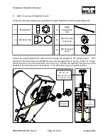
Page 18: ...knob the M6 hex nut and the upper knob to the top of the rod Finally thread the acorn nut onto the bottom end of the rod Ensure the distance from the top of the bracket to the tip of the acorn nut is approx 7 in 178 mm for ease of adjustment later 1x M6 Hex Nut 1x Depth Adjustment Rod 1x M6 Acorn Nut 1x M6 Thru Hole Lock Knob 1x M6 Threaded Knob BBS MY2020 EN Rev A Page of 16 52 19 May 2020 7 in 1...

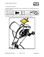
Page 19: ...head assembly secure the grinding shield to the grinding head using the hardware listed below Using a T20 Torx screwdriver secure the shield to the grinding head as shown 1x 8 X 0 375 Torx Self Tapping Screw 1x Grinding Shield BBS MY2020 EN Rev A Page of 17 52 19 May 2020 ...

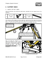
Page 20: ... arm is below the right arm Secure both arms to the base and control box using the M6 4 lobe knob Note If mounting the sharpener to a workbench fasten the inner support arms to the mounting base using the extra M6 X 14 mm hex bolt instead of the M6 4 lobe knob See section WORKBENCH MOUNTING for more information 1x M6 4 Lobe Knob 2x Inner Support Arm BBS MY2020 EN Rev A Page of 18 52 19 May 2020 WO...

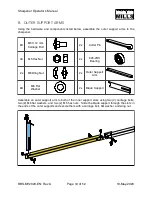
Page 21: ...arms using two 2 carriage bolts two 2 M6 flat washers and two 2 M5 hex nuts Slide the blade support through the slots in the ends of the outer supports and secure them with a carriage bolt flat washer and wing nut 6X M5 X 12 mm Carriage Bolt 2x Cotter Pin 4X M5 Hex Nut 2x 626 2RS Bearing 2x M5 Wing Nut 2x Outer Support Arm 8X M6 Flat Washer 2x Blade Support BBS MY2020 EN Rev A Page of 19 52 19 May...

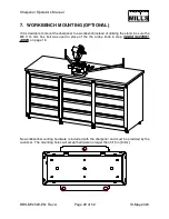
Page 22: ...g the stand be sure the M6 X 14 mm hex bolt was used in place of the the 4 lobe knob in step INNER SUPPORT ARMS on page 16 No workbench mounting hardware is included with the sharpener and must be provided by the customer The mounting holes will accept hardware no larger than 5 16 in 8 mm BBS MY2020 EN Rev A Page of 20 52 19 May 2020 ...

Page 23: ... control box connect the POSITIVE clamp red to the positive battery terminal and the NEGATIVE clamp black to the negative battery terminal 1x 12 V Battery BBS MY2020 EN Rev A Page of 21 52 19 May 2020 Always remember to check that the toggle switches are in the STOP position before connecting the battery BATTERY POLARITY LABEL TOGGLE SWITCH LABEL ...

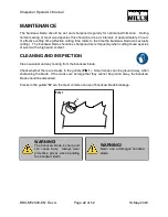
Page 24: ...s of wood with a high sand content CLEANING AND INSPECTION Clean sawdust and any coating from the bandsaw blade Check whether there are cracks in the gullets FIG 1 Small cracks can be ground away when sharpening the blade If the cracks are so large that they cannot be ground away the bandsaw blade should be discarded Cracks in the gullets G are the most common cause of bandsaw blade breakage BBS M...

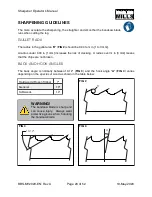
Page 25: ... risk of cracking A radius over in 3 mm means that the chips are not broken BACK AND HOOK ANGLES The back angle is normally between 10 12 FIG 3 and the hook angle A FIG 4 varies depending on the species of wood as shown in the table below Hardwoods Frozen Timber 7 General 10 Softwoods 14 BBS MY2020 EN Rev A Page of 23 52 19 May 2020 FIG 4 A FIG 2 R FIG 3 10 12 The bandsaw blade is sharp and can ca...

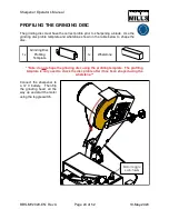
Page 26: ...e disc Note do not shape the grinding disc using the profiling template The profiling template is only used to check the disc profile after it has been shaped using the whetstone Connect the sharpener to a 12 V battery Then flip the grinding head all the way up and start the motor using the toggle switch 1x Grinding Disc Profiling Template 1x Whetstone BBS MY2020 EN Rev A Page of 24 52 19 May 2020...

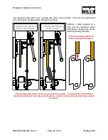
Page 27: ...e Tooth profiles from different blade manufacturers can vary and therefore custom grinding disc profiles may need to be made BBS MY2020 EN Rev A Page of 25 52 19 May 2020 Use the whetstone to shape the disc Remove a little material at a time with the whetstone while periodically checking the profile with the profiling template Turn the grinding wheel off before using the template Grinding disc pro...

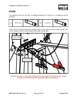
Page 28: ... the connector that is inline with the wiring harness and the 15 A fuse is inside connector on the positive red battery clamp cable Always be sure to connect the sharpener to an approved 12 V power source Higher voltages could waste fuses and possibly damage the machine 2x 0 5 A Fuse 2x 15 A Fuse BBS MY2020 EN Rev A Page of 26 52 19 May 2020 15 A Fuse 0 5 A Fuse ...

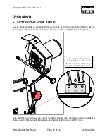
Page 29: ...blade to be sharpened Once set tighten the locking knob Note that the grinding head can be set to custom angles other than the three 3 predefined angles shown Simply rotate the head as desired and lock it in place with the knob BBS MY2020 EN Rev A Page of 27 52 19 May 2020 The detent in the grinding head shaft seats into one of the 3 predefined lock points in the back of the control box ...

Page 30: ...d to accommodate shorter blades With the bearings on the inside of the blade as shown below it prevents the blade from catching as it moves BBS MY2020 EN Rev A Page of 28 52 19 May 2020 Weld seam Keep the weld seam left of the grinding disc so it does not interfere with the setup process The tooth spacing at the weld can vary slightly from the rest of the blade due to the welding tolerance STANDAR...

Page 31: ...e knob on the pressure plate until it bottoms out The blade should slide left but not move in or out forwards or backwards BBS MY2020 EN Rev A Page of 29 52 19 May 2020 Rotate the advancer up when installing the blade on the control box If the blade is too loose or too tight the jam nut can be turned in or out to ensure proper pressure on the blade is achieved ...

Page 32: ...attery polarity label on top of the control box connect the POSITIVE clamp red to the positive battery terminal and the NEGATIVE clamp black to the negative battery terminal BBS MY2020 EN Rev A Page of 30 52 19 May 2020 Always remember to check that the toggle switches are in the STOP position before connecting the battery BATTERY POLARITY LABEL TOGGLE SWITCH LABEL ...

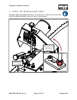
Page 33: ... 52 19 May 2020 Advancer toggle switch on If the cam is turning clockwise turn off the machine and reverse the battery polarity Adjust jam nut behind pressure plate knob if gear motor is straining Listen to the gear motor as the blade advances If it gets loud and sounds like it is straining the blade is too tight Adjust the jam nut behind the pressure plate knob Turn off the toggle switch once the...

Page 34: ...WN Manually rotate the grinding head down do not turn it on Seat the acorn nut at the end of the depth adjustment rod into the hole in the stop plate BBS MY2020 EN Rev A Page of 32 52 19 May 2020 Seat acorn nut into hole in stop plate Both toggle switches off ...

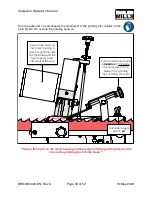
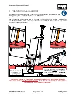
Page 35: ... and be ready to lift the grinding head on the chance the grinding disc hits the blade BBS MY2020 EN Rev A Page of 33 52 19 May 2020 Advancer toggle switch on Keep a free hand on the motor housing in case the grinding disc hits the blade and the head needs to be lifted out of the way Turn the advancer knob clockwise to increase the movement of the blade if the grinding disc is hitting the teeth ...

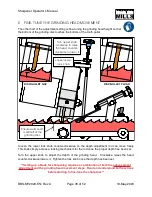
Page 36: ...e counter clockwise will back off the advancer and reduce the blade s leftward movement Setting up a blade for sharpening requires a combination of both the advancement adjustment and the grinding head movement steps Read and understand both sections before starting to fine tune the sharpener BBS MY2020 EN Rev A Page of 34 52 19 May 2020 Ensure weld seam is still left of the grinding disc DISC TOO...

Page 37: ... set Turn the upper knob to adjust the depth of the grinding head Clockwise raises the head counter clockwise lowers it Tighten the lock knob once the depth has been set Setting up a blade for sharpening requires a combination of both the advancement adjustment and the grinding head movement steps Read and understand both sections before starting to fine tune the sharpener BBS MY2020 EN Rev A Page...

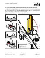
Page 38: ...ust the position of the stop plate by flipping up the lever and loosening the M5 socket head cap screw and lock nut This adjustment will allow the grinding disc to clear the tooth as it exits the gullet Retighten the cap screw and lock nut after moving the stop plate BBS MY2020 EN Rev A Page of 36 52 19 May 2020 Flip up the lever to loosen the lock nut under the stop plate ...

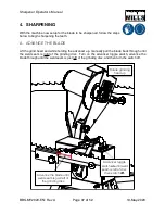
Page 39: ... pull the blade back through until the weld seam is right of the grinding disc Turn on the advancer toggle switch advance the blade through until the weld seam is just left of the grinding disc and then turn the switch off BBS MY2020 EN Rev A Page of 37 52 19 May 2020 Advance the blade until weld seam is just left of the grinding disc Rotate grinding head up Advancer toggle switch on until weld se...

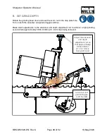
Page 40: ...e switches Make small adjustments to the advancer and depth adjustment rod to achieve a light grinding sound where approximately 0 004 0 008 in 0 1 0 2 mm is being removed BBS MY2020 EN Rev A Page of 38 52 19 May 2020 Advancer and grinder toggle switches on Adjust the advancer and depth adjustment rod so that approximately 0 004 0 008 in 0 1 0 2 mm is being removed ...

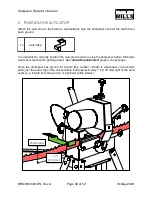
Page 41: ...the sharpener before the blade weld seam reaches the grinding head See Auto Stop Activated graphic on next page Once the sharpener has ground 6 10 teeth the number of teeth is dependant on the blade pitch set the auto stop on the closest blade tooth approximately 7 in 178 mm right of the weld seam e g 8 teeth from the weld on in 22 mm pitch blades 1x Auto Stop BBS MY2020 EN Rev A Page of 39 52 19 ...

Page 42: ...am reaches the grinding disc The last tooth can be ground manually by moving the blade and lowering the grinding head by hand to sharpen the hook face BBS MY2020 EN Rev A Page of 40 52 19 May 2020 The auto stop triggers the toggle switches shutting off the sharpener Weld seam 7 in 178 mm AUTO STOP ACTIVATED Manually grind last tooth ...

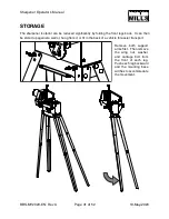
Page 43: ...be stored up against a wall or hung from it or fit in the back of a vehicle for easier transport BBS MY2020 EN Rev A Page of 41 52 19 May 2020 Remove both support arms first Then remove the wing nut washer and carriage bolt from the front of each leg Push each leg backward and the mounting base will flex to accommodate the movement ...

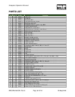
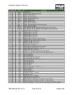
Page 44: ...ER 22 1 0001560 BLADE STOP 23 1 0001587 STOP PLATE 24 1 0003805 CAM 25 1 0001586 CONNECTING ARM 26 1 0003985 TORSION SPRING HOOK ENDS 0 575 in OD 0 045 in DIA WIRE 5 COILS 27 1 0003988 OUTER MOUNTING ARM 28 1 0003989 INNER MOUNTING ARM 29 1 0003984 KNOB MULTI LOBE 48 mm OD M10 X 1 5 40 mm LG 30 1 0001566 GRINDING WHEEL HOUSING 31 1 0003780 DC MOTOR 12 VDC 32 1 0001553 GRINDING DISC 152 mm OD 6 mm ...

Page 45: ... M6 X 1 55 mm LG 67 1 HDW SHCS M5 X 0 8 14 mm LG 68 22 HDW CARRIAGE BOLT SQ NECK M5 X 0 8 12 mm LG 69 1 HDW SET SCREW CUP POINT M6 X 1 10 mm LG 70 4 HDW SCREW PFH M4 X 0 7 8 mm LG 71 2 HDW SCREW TPH T20 DRIVE 8 4 2 mm 3 8 in 9 5 mm LG 72 13 HDW SCREW TPH T20 DRIVE 8 4 2 mm 3 8 in 9 5 mm LG BLACK 73 32 HDW FLAT WASHER M6 74 3 HDW FLAT WASHER M10 75 2 HDW FENDER WASHER M6 28 mm OD 76 2 HDW FENDER WA...

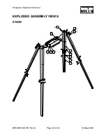
Page 46: ...Sharpener Operator s Manual EXPLODED ASSEMBLY VIEWS STAND BBS MY2020 EN Rev A Page of 44 52 19 May 2020 ...

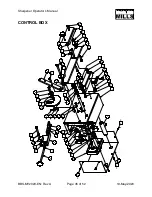
Page 47: ...Sharpener Operator s Manual CONTROL BOX BBS MY2020 EN Rev A Page of 45 52 19 May 2020 ...

Page 48: ...Sharpener Operator s Manual GRINDING HEAD BBS MY2020 EN Rev A Page of 46 52 19 May 2020 ...

Page 49: ...Sharpener Operator s Manual CONTROL HEAD TO STAND BBS MY2020 EN Rev A Page of 47 52 19 May 2020 ...

Page 50: ...Sharpener Operator s Manual ACCESSORIES AND LABELS BBS MY2020 EN Rev A Page of 48 52 19 May 2020 ...

Page 51: ...Sharpener Operator s Manual NOTES BBS MY2020 EN Rev A Page of 49 52 19 May 2020 ...

Page 52: ...Sharpener Operator s Manual BBS MY2020 EN Rev A Page of 50 52 19 May 2020 ...

Page 53: ...Sharpener Operator s Manual BBS MY2020 EN Rev A Page of 51 52 19 May 2020 ...

Page 54: ...Sharpener Operator s Manual BBS MY2020 EN Rev A Page of 52 52 19 May 2020 ...

Page 55: ......

Page 56: ......

Reviews: