background image


SST-DN3-PCI-1 and SST-DN3-PCI-2 


Hardware Reference Guide


Installation  

25 

©2004 Woodhead Software & Electronics, Division of Woodhead Canada Limited 

Document Edition: 1.1, Document #: 715-0083, Template Edition: 1.1, Template #: QMS-06-045 

Use, duplication or disclosure of this document or any of the information contained herein is subject to the restrictions on page ii of this document.


2.3  Installing the Card 

To install the card in your computer: 

1.  Ensure that all power to your computer is off. 

2. Adequately ground yourself, as cautioned in Section 2.2, 

Handling Precautions

3.  Unplug the power cord, modem (if applicable), and any network cables. 

4.  Remove the computer cover. Consult your computer user’s guide for information on 

installing add-in boards. 

5.  Take the card out of its shipping container and anti-static bag, being careful not to touch 

any of the connectors or pins. 

6.  Firmly press the card into a compatible PCI-compliant connector. 

7.  Secure the card using the screws provided. Re-connect any items unplugged in Step 3. 

8.  Replace the computer cover and power up the machine. 

9.  Connect the card to the DeviceNet network, as explained in the following section. 

10. Replace the computer cover and power up the machine. 

Artisan Technology Group - Quality Instrumentation ... Guaranteed | (888) 88-SOURCE | www.artisantg.com

Summary of Contents for SST-DN3-PCI-1

Page 1: ...l service in house repair center WE BUY USED EQUIPMENT Sell your excess underutilized and idle used equipment We also offer credit for buy backs and trade ins www artisantg com WeBuyEquipment REMOTE INSPECTION Remotely inspect equipment before purchasing with our interactive website at www instraview com LOOKING FOR MORE INFORMATION Visit us on the web at www artisantg com for more information on ...

Page 2: ...SST DN3 PCI 1 and SST DN3 PCI 2 Hardware Reference Guide Document Edition 1 1 Document 715 0083 Artisan Technology Group Quality Instrumentation Guaranteed 888 88 SOURCE www artisantg com ...

Page 3: ...property of Woodhead Industries Inc and or its subsidiaries and may not be used or disclosed to others without the express prior written consent of Woodhead Industries Inc and or its subsidiaries SST is a trademark of Woodhead Software Electronics All other trade names are trademarks or registered trademarks of their respective companies At Woodhead we strive to ensure accuracy in our documentatio...

Page 4: ...nt 715 0083 Template Edition 1 1 Template QMS 06 045 Use duplication or disclosure of this document or any of the information contained herein is subject to the restrictions on page ii of this document Preface Preface Sections Purpose of this Guide Using this Guide Conventions Artisan Technology Group Quality Instrumentation Guaranteed 888 88 SOURCE www artisantg com ...

Page 5: ...loadable application firmware modules which enable application level product behavior For more details refer to relevant firmware documentation Note An application running on one channel does not affect the performance of other channels as it does not share memory or processor resources with them Note In this manual the SST DN3 PCI 1 and SST DN3 PCI 2 will be referred to as the card except where p...

Page 6: ...r understanding Style The following stylistic conventions are used throughout this guide Bold indicates field names button names tab names and options or selections Italics indicates keywords indexed or instances of new terms and or specialized words that need emphasis CAPS indicates a specific key selection such as ENTER TAB CTRL ALT DELETE Code Font indicates command line entries or text that yo...

Page 7: ...e used throughout this guide Card the SST DN3 PCI 1 or SST DN3 PCI 2 network interface card Channel a DeviceNet network interface on the card Firmware Module the embedded software module that gets loaded to the card s memory and runs on the card This is the operating system of the card enabling it to respond to commands from the host and manage network communications Host the computer system in wh...

Page 8: ...t this guide Warning Warning messages alert the reader to situations where personal injury may result Warnings are accompanied by the symbol shown and precede the topic to which they refer Caution Caution messages alert the reader to situations where equipment damage may result Cautions are accompanied by the symbol shown and precede the topic to which they refer Note A note provides additional in...

Page 9: ...da Limited Document Edition 1 1 Document 715 0083 Template Edition 1 1 Template QMS 06 045 Use duplication or disclosure of this document or any of the information contained herein is subject to the restrictions on page ii of this document Artisan Technology Group Quality Instrumentation Guaranteed 888 88 SOURCE www artisantg com ...

Page 10: ... Purpose of this Guide iv Using this Guide iv Conventions v Style v Terminology vi Special Notation vii Card Overview 13 1 1 Warnings and Cautions 14 1 2 Card Features 15 1 3 Byte Ordering 15 1 4 DN3 Compatibility Overview 16 1 5 Hardware Description 17 1 5 1 CAN Connector 18 1 5 2 LEDs 20 Installation 23 2 1 System Requirements 24 2 2 Handling Precautions 24 2 3 Installing the Card 25 2 4 Connect...

Page 11: ... 3 5 BankSize Register 37 3 3 6 HostIrq Register 38 3 3 7 LedReg Register 38 3 3 8 Debug Register 39 3 3 9 Host Data Register FamilyID 39 Troubleshooting 41 4 1 HLTH LED is Red 42 4 2 Memory Conflict 43 4 3 Card Not Found 43 4 4 General Troubleshooting 43 Error Messages 45 A 1 Introduction 46 A 2 FamilyID Messages 46 A 3 Fatal Hardware Self Test Flash Codes 46 Technical Specifications 47 B 1 Techn...

Page 12: ...ion 1 1 Document 715 0083 Template Edition 1 1 Template QMS 06 045 Use duplication or disclosure of this document or any of the information contained herein is subject to the restrictions on page ii of this document CE Compliance 61 E 1 CE Compliance 62 Index 63 Artisan Technology Group Quality Instrumentation Guaranteed 888 88 SOURCE www artisantg com ...

Page 13: ...da Limited Document Edition 1 1 Document 715 0083 Template Edition 1 1 Template QMS 06 045 Use duplication or disclosure of this document or any of the information contained herein is subject to the restrictions on page ii of this document Artisan Technology Group Quality Instrumentation Guaranteed 888 88 SOURCE www artisantg com ...

Page 14: ...ion 1 1 Template QMS 06 045 Use duplication or disclosure of this document or any of the information contained herein is subject to the restrictions on page ii of this document 1 Card Overview Chapter Sections Warnings and Cautions Card Features Byte Ordering DN3 Compatibility Overview Hardware Description Artisan Technology Group Quality Instrumentation Guaranteed 888 88 SOURCE www artisantg com ...

Page 15: ...nderstand this guide in its entirety before proceeding Failure to observe this precaution could result in severe bodily injury or in extreme cases loss of life Warning You must provide an external hard wired emergency stop circuit outside the programmable controller circuitry This circuit must disable the system in case of improper operation Uncontrolled machine motion may result if this procedure...

Page 16: ...re Processor 256 KB of shared RAM DeviceNet compliant 5 pin CAN connector Data rate of up to 1 Mbaud for CAN and 125K 250K and 250K for DeviceNet Bi color LEDs showing card status Isolated CAN physical layer on each channel Compatible with CAN specification 2 0 part A and part B 1 3 Byte Ordering The card uses Intel style little endian byte ordering for multi byte entities LSB low address and MSB ...

Page 17: ...V 2 1 1 Optional Required Not supported Supported 2 2 Required Required Supported Supported 2 3 Required Required Supported Not supported SST Product SST DN3 PCI 1 and SST DN3 PCI 2 Required Required 2 Supported 2 Supported 1 The card requires both 3 3V and 5V to be supplied by the motherboard Because 3 3V supply voltage is optional in PCI specification revision 2 1 the card may not function in so...

Page 18: ...ocument 1 5 Hardware Description The main features of the card are described in more detail in the following sections For information on card dimensions refer to Section B 1 Technical Specifications Figure 1 The SST DN3 PCI 1 and 2 Interface Card Table 2 Card Components Feature Description 1 Channel A HLTH LED 2 Channel A CAN Connector 3 Channel A COMM LED 4 Channel B HLTH LED 5 Channel B CAN Conn...

Page 19: ...hat conforms to the standard DeviceNet pinout Pin numbers names and color codes are identified in the figure below Figure 2 5 Pin CAN Connector 1 2 3 4 5 CANH V CANL V SHIELD Pin Name DeviceNetTM Color Code White Red Blue Black Bare 1 5 1 1 V V These terminals provide power to the isolated section of the network interface and must be connected in order for the card to function On DeviceNet network...

Page 20: ...NL These are the CAN communication bus signal terminals Use only shielded twisted pair cable 1 5 1 3 SHIELD This is the shield connector This terminal is snubbed to the PC PCI chassis ground via a 1M ohm resistor Note According to the DeviceNet specification the snubber circuit can be omitted if the card has no local connection to ground Note The shield should be connected directly to earth ground...

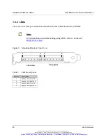
Page 21: ...in is subject to the restrictions on page ii of this document 1 5 2 LEDs There are two LEDs per channel Health HLTH and Communications COMM Note For information on troubleshooting using LEDs refer to Section 4 1 HLTH LED is Red Figure 3 Mounting Bracket Front View Table 3 LED Descriptions Feature Description 1 Channel A HLTH LED 2 Channel A COMM LED 3 Channel B HLTH LED 4 Channel B COMM LED 1 2 Ch...

Page 22: ... initialization failed or the card is not powered Green The firmware is loaded and running Red The card has not loaded an error occurred during the load or there is a firmware run time error Amber Startup self test complete no firmware loaded The firmware must be reloaded refer to Section 4 1 HLTH LED is Red Note If the HEALTH LED is flashing there may have been a startup failure For more details ...

Page 23: ...nada Limited Document Edition 1 1 Document 715 0083 Template Edition 1 1 Template QMS 06 045 Use duplication or disclosure of this document or any of the information contained herein is subject to the restrictions on page ii of this document Artisan Technology Group Quality Instrumentation Guaranteed 888 88 SOURCE www artisantg com ...

Page 24: ...e Edition 1 1 Template QMS 06 045 Use duplication or disclosure of this document or any of the information contained herein is subject to the restrictions on page ii of this document 2 Installation Chapter Sections System Requirements Handling Precautions Installing the Card Connecting to a Network Artisan Technology Group Quality Instrumentation Guaranteed 888 88 SOURCE www artisantg com ...

Page 25: ... to Section 1 4 DN3 Compatibility Overview for more compatibility details If interrupts are required you will need a physical interrupt On the 2 channel card this will be shared between channels 2 2 Handling Precautions The card contains components that are sensitive to electrostatic discharge ESD Do not touch it without following these precautions Caution Always follow correct ESD procedures befo...

Page 26: ...ing Precautions 3 Unplug the power cord modem if applicable and any network cables 4 Remove the computer cover Consult your computer user s guide for information on installing add in boards 5 Take the card out of its shipping container and anti static bag being careful not to touch any of the connectors or pins 6 Firmly press the card into a compatible PCI compliant connector 7 Secure the card usi...

Page 27: ...djacent terminal Directly connecting DeviceNet thick cable to the card is not recommended due to the mechanical stress that the cable places on the connector If you must attach thick cable secure it to prevent undue stress 2 4 1 1 Termination The card does not have a built in termination resistor Each network must have two termination resistors one at each end of the trunk Always refer to the Devi...

Page 28: ...to the 5 pin connector and tighten all screws Make sure that all strands of wire go into the connector as bent strands may cause shorts to an adjacent terminal 2 4 2 1 Termination The card does not have a built in termination resistor You must add termination in accordance with the requirements of the target CAN network 2 4 2 2 Power If the CAN Network does not supply 11 24 VDC power connect an ex...

Page 29: ...nada Limited Document Edition 1 1 Document 715 0083 Template Edition 1 1 Template QMS 06 045 Use duplication or disclosure of this document or any of the information contained herein is subject to the restrictions on page ii of this document Artisan Technology Group Quality Instrumentation Guaranteed 888 88 SOURCE www artisantg com ...

Page 30: ...3 Template Edition 1 1 Template QMS 06 045 Use duplication or disclosure of this document or any of the information contained herein is subject to the restrictions on page ii of this document 3 Hardware Register Details Chapter Sections Introduction Card Configuration Space Card Configuration Registers Artisan Technology Group Quality Instrumentation Guaranteed 888 88 SOURCE www artisantg com ...

Page 31: ...on The following information is intended for programmers familiar with hardware level PC programming 3 2 Card Configuration Space This section provides card configuration details for the card Note Refer to the PCI specification and your particular OS documentation for the function of all other PCI configuration space registers and their typical uses Note Typically the PCI configuration space regis...

Page 32: ...00 Header ID 0x00 PCI Latency 0x00 CacheLineSize 0x00 Y 7 0 0010H PCI Base Address 0 for Memory Mapped Config Registers Y 0014H PCI Base Address 1 for I O Mapped Config Registers Y 0018H PCI Base Address 2 for Local Address Space 0 Shared RAM Access Window for all channels Y 001CH PCI Base Address 3 for Local Address Space 1 I O Space Access Window for all channels Y 0020H PCI Base Address 4 for L...

Page 33: ...mmended that applications wait up to 2 seconds Initialization can be confirmed by monitoring the LEDs or by reading the FamilyID register as described in Section C 1 1 Verify Card Presence Table 6 Host Register Layout The following offsets are offsets from the base address An X means that the bit is reserved writing to it will result in undefined behavior Offset Register Bit Name Name 7 6 5 4 3 2 ...

Page 34: ... flag it will be Flag 0 Table 8 Control Register Bit Descriptions Bit Name Description CardRun This bit controls and indicates whether or not the channel s processor is running It also affects the Health LED When this bit is 0 the processor is halted and the LED is RED When this bit is 1 the processor is running normally and the LED is under channel processor control When this bit is 1 and watchdo...

Page 35: ...This bit is used by the channel s processor to indicate that the channel generated an interrupt If IntEn is set to 1 this also means that the channel generated a physical interrupt on the PCI bus Writing 1 acknowledges the interrupt and clears it Writing 0 has no effect Reading 1 indicates interrupt in progress Reading 0 indicates interrupt complete CardIrq1 This bit is used by the host to send in...

Page 36: ...a value of x indicates don t care Bit and Value Window Size and Bank Number BA19 BA18 BA17 BA16 BA15 BA14 BA13 BA12 8k 16k 32k 64k 128k 256k x x 0 0 0 0 0 x 0 0 0 0 0 0 x x 0 0 0 0 1 x 1 0 0 0 0 0 x x 0 0 0 1 0 x 2 1 0 0 0 0 x x 0 0 0 1 1 x 3 1 0 0 0 0 x x 0 0 1 0 0 x 4 2 1 0 0 0 x x 0 0 1 0 1 x 5 2 1 0 0 0 x x 0 0 1 1 0 x 6 3 1 0 0 0 x x 0 0 1 1 1 x 7 3 1 0 0 0 x x 0 1 0 0 0 x 8 4 2 1 0 0 x x 0 1...

Page 37: ... x 29 14 7 3 1 0 x x 1 1 1 1 0 x 30 15 7 3 1 0 x x 1 1 1 1 1 x 31 15 7 3 1 0 x don t care Table 11 Bank Address Register Bit Descriptions Bit Name Description BA17 13 Each channel has 256k of memory accessible to the host The Bank Address bits select which bank of memory the host can access For example in 16k mode the bank number may be 0 through 15 or 0x0 0xf BA17 BA13 represent the bank address ...

Page 38: ...0 0 1 1 Table 13 BankSize Register Values In this table the default window values are highlighted Bit and Value Window Size Description WS19 WS18 WS17 WS16 WS15 WS14 WS13 WS12 0 0 0 0 0 0 0 1 8K BA19 BA13 used BA12 ignored 0 0 0 0 0 0 1 1 16K BA19 BA14 used BA13 BA12 ignored 0 0 0 0 0 1 1 1 32K BA19 BA15 used BA14 BA12 ignored 0 0 0 0 1 1 1 1 64K BA19 BA16 used BA15 BA12 ignored 0 0 0 1 1 1 1 1 12...

Page 39: ...ster This register is reserved 3 3 7 LedReg Register This register reflects the state of the channel s LEDs allowing host software to monitor the LEDs and display them on screen Table 15 LedReg Register Settings PWR HLTH COMM Bit 7 6 5 4 3 2 1 0 Name Reserved PwrRed PwrGrn HealthRed HealthGrn CommRed CommGrn Read Write R R R R R R R R Reset 0 0 0 0 0 0 0 0 Note Although the card does not have a ph...

Page 40: ...power state 0 0 1 1 0 1 0 1 Invalid LED is green LED is red Invalid HealthRed HealthGrn These bits indicate the channel s health LED state 0 0 1 1 0 1 0 1 LED is off LED is green LED is red LED is amber CommRed CommGrn These bits indicate the channel s communications LED state 0 0 1 1 0 1 0 1 LED is off LED is green LED is red LED is amber 3 3 8 Debug Register This register is reserved 3 3 9 Host ...

Page 41: ...ead Canada Limited Document Edition 1 1 Document 715 0083 Template Edition 1 1 Template QMS 06 045 Use duplication or disclosure of this document or any of the information contained herein is subject to the restrictions on page ii of this document Artisan Technology Group Quality Instrumentation Guaranteed 888 88 SOURCE www artisantg com ...

Page 42: ... Troubleshooting Chapter Sections HLTH LED is Red Memory Conflict Card Not Found General Troubleshooting For a list of hardware related errors that can be generated by the card refer to Appendix A Error Messages Warning Only qualified electrical personnel familiar with the construction and operation of this equipment and the hazards involved should install adjust operate or service this equipment ...

Page 43: ...hooting a red HLTH LED Note For information on LED flash codes refer to Section A 3 Fatal Hardware Self Test Flash Codes If the HLTH LED is red the channel is not running or there has been a firmware run time error Check the WdTout bit refer to Table 8 Control Register Bit Descriptions to determine whether or not there has been a watchdog timeout and consult the appropriate firmware manual if nece...

Page 44: ...ge resources review the requirements of the other hardware installed in the machine to select a non conflicting memory window If you continue to experience difficulties refer to Section 4 4 General Troubleshooting 4 3 Card Not Found If a card not found message is displayed check for memory I O and IRQ conflicts If you continue to experience difficulties refer to Section 4 4 General Troubleshooting...

Page 45: ...anada Limited Document Edition 1 1 Document 715 0083 Template Edition 1 1 Template QMS 06 045 Use duplication or disclosure of this document or any of the information contained herein is subject to the restrictions on page ii of this document Artisan Technology Group Quality Instrumentation Guaranteed 888 88 SOURCE www artisantg com ...

Page 46: ...ent 715 0083 Template Edition 1 1 Template QMS 06 045 Use duplication or disclosure of this document or any of the information contained herein is subject to the restrictions on page ii of this document A Error Messages Appendix Sections Introduction FamilyID Messages Flashing LEDs Artisan Technology Group Quality Instrumentation Guaranteed 888 88 SOURCE www artisantg com ...

Page 47: ...ero 0 bit shown as a red LED This will occur for a period of 900ms followed by 100ms of off time The LSB will be followed by an additional 1000ms of off time after which the sequence will repeat The following table describes each possible fault code Table 17 LED Flash Codes Value Name Description 01 BITTEST8 Bit test failure of an 8 bit memory range 02 BITTEST16 Bit test failure of a 16 bit memory...

Page 48: ... 1 1 Document 715 0083 Template Edition 1 1 Template QMS 06 045 Use duplication or disclosure of this document or any of the information contained herein is subject to the restrictions on page ii of this document B Technical Specifications Appendix Sections Technical Specifications Artisan Technology Group Quality Instrumentation Guaranteed 888 88 SOURCE www artisantg com ...

Page 49: ...g Typical Current Draw 5V 5 1 03A 2 channel Table 19 Network Specifications Cable Shielded twisted pair compatible with target network External Power 11 24 VDC 50mA typical Isolation 500V Protocol CAN 2 0 A B Data Rate Up to 1 Mbaud for CAN 125K 250K and 500K baud for DeviceNet Table 20 PCI Bus Specifications Compliance Compliant with PCI 2 2 will operate in 2 3 and some 2 1 compliant systems Refe...

Page 50: ...tion 1 1 Template QMS 06 045 Use duplication or disclosure of this document or any of the information contained herein is subject to the restrictions on page ii of this document Figure 4 Card Dimensions For information on card components refer to Section 1 5 Hardware Description 1 and 2 channel 2 channel only Legend Artisan Technology Group Quality Instrumentation Guaranteed 888 88 SOURCE www arti...

Page 51: ...ead Canada Limited Document Edition 1 1 Document 715 0083 Template Edition 1 1 Template QMS 06 045 Use duplication or disclosure of this document or any of the information contained herein is subject to the restrictions on page ii of this document Artisan Technology Group Quality Instrumentation Guaranteed 888 88 SOURCE www artisantg com ...

Page 52: ...document or any of the information contained herein is subject to the restrictions on page ii of this document C Loading Firmware Appendix Sections Loading Firmware Note This appendix describes how to load the card manually or how to write your own loader If you are using a Windows loader provided by Woodhead Software Electronics the following instructions are not required Artisan Technology Group...

Page 53: ... driver for the card or producing a stand alone embedded application the following section describes the basic sequence of steps to load a module into the channel s memory Note These procedures should be repeated for each channel Note For register descriptions refer to Chapter 3 Hardware Register Details C 1 1 Verify Card Presence To verify the channel s presence follow these steps 1 Start up your...

Page 54: ...rite zero 0 to the Control Register to disable the channel 2 Read a word from the target memory window and save it 3 Write 0xAA55 to the target address 4 Read the target address It should not contain 0xAA55 5 If 0xAA55 is read a conflict exists Perform the following steps Restore the saved value to the target address Abort the load procedure Examine the resource allocations in your operating syste...

Page 55: ...the channel s RAM follow these steps 1 Write the desired window size to the BankSize register refer to Section 3 3 5 BankSize Register for details 2 Write 0x40 MemEn to the Control Register 3 Set the Bank Address Register refer to Section 3 3 4 Bank Address Register for details 4 Fill the shared memory with a test pattern Note We recommend using a test pattern with a unique value for each word in ...

Page 56: ...ntire firmware file into shared memory starting at bank zero 0 offset zero 0 2 If the application requires interrupts from the card bit wise OR value 0x20 IntEn to the Control Register 3 Bit wise OR value 0x80 CardRun to the Control Register to start the firmware module 4 Start a 2 second timeout timer and wait for value 0x04 HostIrq0 in the Control Register to set 5 If the timer expires the firmw...

Page 57: ...Canada Limited Document Edition 1 1 Document 715 0083 Template Edition 1 1 Template QMS 06 045 Use duplication or disclosure of this document or any of the information contained herein is subject to the restrictions on page ii of this document Artisan Technology Group Quality Instrumentation Guaranteed 888 88 SOURCE www artisantg com ...

Page 58: ...nt 715 0083 Template Edition 1 1 Template QMS 06 045 Use duplication or disclosure of this document or any of the information contained herein is subject to the restrictions on page ii of this document D Warranty and Support Appendix Sections Warranty Reference Documents Technical Support Artisan Technology Group Quality Instrumentation Guaranteed 888 88 SOURCE www artisantg com ...

Page 59: ...lication March 2002 http www odva org PCI Local Bus Specification v2 2 PCI Special Interest Group December 1998 PCI9030 Datasheet v1 4 PLX Technology Publications May 2002 SST DN3 PCI and 5136 DNP PCI Comparison Technical Note http www mysst com download D 3 Technical Support Please ensure that you have the following information readily available before calling for technical support Card model typ...

Page 60: ...cumentation and software updates are also available on the website Note If you are using the card with a third party application refer to the documentation for that package for information on configuring the software for the card North America Canada Tel 1 519 725 5136 Fax 1 519 725 1515 Email techsupportna woodhead com Europe France Tel 33 0 2 32 96 04 22 Fax 33 0 2 32 96 04 21 Email supportfr ap...

Page 61: ... information contained herein is subject to the restrictions on page ii of this document Asia Pacific Japan Tel 81 452 24 3560 Fax 81 52 745 7622 Email techsupport woodhead co jp Singapore Tel 65 64 67 96 52 Fax 65 6261 3588 Email info woodhead com sg China Tel 86 21 5032 8080 Fax 86 21 5031 8833 Email techsupport woodhead co jp For the most current contact details please visit http www woodhead c...

Page 62: ...ition 1 1 Document 715 0083 Template Edition 1 1 Template QMS 06 045 Use duplication or disclosure of this document or any of the information contained herein is subject to the restrictions on page ii of this document E CE Compliance Appendix Sections CE Compliance Artisan Technology Group Quality Instrumentation Guaranteed 888 88 SOURCE www artisantg com ...

Page 63: ...ay cause radio interference in which case you may be required to take adequate measures Caution This equipment is neither designed for nor intended for operation in installations where it is subject to hazardous voltages and hazardous currents Marking of this equipment with the symbol indicates compliance with European Council Directive 89 336 EEC The EMC Directive as amended by 92 31 EEC and 93 6...

Page 64: ...ng 15 cautions 14 24 62 CE compliance 62 compared to DNP card 16 connecting to a network 26 definition of vi error messages 46 features of 15 hardware 17 installing 25 loading firmware to 52 registers 32 status of 20 system requirements 24 technical specifications 48 technical support 58 troubleshooting 42 warnings 14 41 62 warranty 58 Card Not Found 43 card presence testing for 52 cautions defini...

Page 65: ...work 27 for DeviceNet network 26 grounding wrist strap 24 H hardware CAN Connector 18 diagram of 17 fatal flash codes 46 LEDs 20 hardware registers 32 height of card 48 HLTH LED description of 21 status of 39 Host Data Register FamilyID 39 Host Register 32 host definition of vi HostIrq Register 38 humidity 48 I installation card 25 firmware 52 interrupts 33 48 isolation 48 L LedReg Register 38 LED...

Page 66: ... R RAM conflicting 53 testing on channels 54 reference documents 58 registers 30 32 requirements system 24 S ss3 files definition of vi status of card 20 of LEDs 38 storage temperature of card 48 support 58 system requirements 24 T technical specifications 48 technical support 58 temperature operating 48 storage 48 termination for CAN network 27 for DeviceNet network 26 testing card presence 52 tr...

Page 67: ...l service in house repair center WE BUY USED EQUIPMENT Sell your excess underutilized and idle used equipment We also offer credit for buy backs and trade ins www artisantg com WeBuyEquipment REMOTE INSPECTION Remotely inspect equipment before purchasing with our interactive website at www instraview com LOOKING FOR MORE INFORMATION Visit us on the web at www artisantg com for more information on ...

Reviews: