background image

24

3062547_201802

17  Siphon/neutralisation/condensate 

pump

For  standard  fuel  oil  EL  (sulphur  content  >  50  ppm), 

neutralisation of the condensate is required.

The neutralisation box must be filled with water 

prior  to  commissioning!  This  checks  whether 

all connections are assembled in a sealed way. 

Operating the device with a leaking connection 

from the neutralisation box carries a risk of waster 

damage from the leaking condensate.

Observe  the  neutralisation  box  installation 

instructions.

Note

If low sulphur fuel oil EL (sulphur content < 50 mg/kg) is used, it 

may be possible to forego neutralisation of the condensate after 

consultation with the lower water authority.

The  condensate  may  only  be  drained  in  drain  lines  in 

accordance with Code of Practice DWA-A251.  


Neutralisation is still required if the condensate has not been 

mixed with sufficient non-domestic waste water (at least 20 times 

the volume of the expected amount of condensate). 

After  removal  of  the  cover,  connect  the  supplied  trap  to  the 

connectors on the combustion chamber pan.

The  sealing  plugs  located  on  the  trap  sealing 

plugs  must  be  removed  before  assembly  of 

the trap, so that the condensate can freely flow 

through  the  trap.  Otherwise,  this  leads  to  an 

operating fault.

With a flexible trap drain hose, form a connection from to the 

on-site drain with a continuous slope (condensate drain level 

from trap 260 mm).

When using a condensate pump, route the flexible trap drain 

hose into the condensate pump and form a connection there to 

the on-site drain.

The  trap  must  be  filled  with  water  prior  to 

commissioning.  Operating  the  appliance  with 

an  empty  trap  presents  a  risk  of  poisoning  or 

asphyxiation  due  to  the  escape  of  flue  gases. 

Undo the trap, remove and fill until water runs 

out of the drain hole on the side. Refit the trap 

and ensure the gasket seals tightly.

If condensate is directly routed to the on-site drain, ventilation 

must be provided so that the drain pipe cannot affect the boiler.

Note

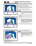
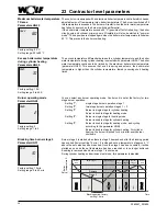
Trap

Drain hose, trap

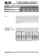
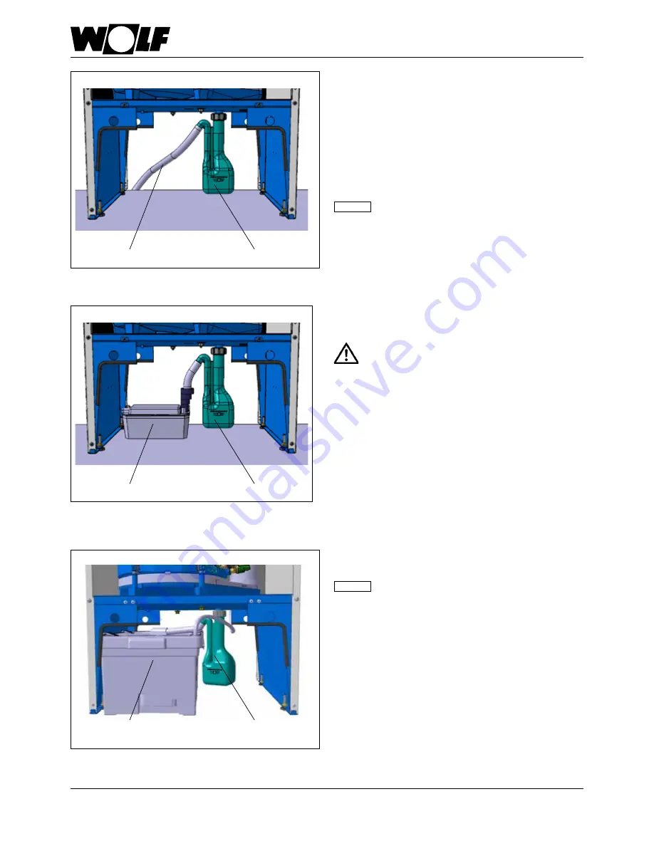
Trap

Condensate pump

Fig.: Example 

drain hose

on the trap

Trap

Neutralising box

(optionally with condensate pump)

Fig.: Example Neutralising box (optionally with 

condensate pump) on the trap

Fig.: Example 

Condensate pump

 on the trap

Summary of Contents for COB

Page 1: ...4 0 FAX 49 0 87 51 74 16 00 www WOLF eu Doc no 3062547_201802 Subject to technical modifications GB Technical guide and installation instructions COB COB TS oil condensing boiler COB for central heating COB TS for central heating with stratification cylinder ...

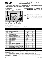
Page 2: ...laying modifying control parameters 30 23 Contractor level parameters 31 Cascade operation 24 Cascade operation technical data control installation information 39 25 Cascade operation Flue gas system design 41 26 Cascade operation Flue gas header design 42 27 Cascade operation Flue gas damper installation 45 28 Cascade operation Flue gas damper installation wiring diagram 46 29 Cascade operation F...

Page 3: ... system user or operator should ensure the safekeeping of all instruction manuals and documents Pass on these installation instructions as well as all other applicable manuals to the system operator or user The following warning symbols are used in these instructions These relate to personal safety and operational reliability Instructions that must be followed precisely in order to prevent risk an...

Page 4: ...ins electrical isolator or heating emergency stop switch and check to ensure that there is no voltage Safeguard the system against reconnection Devices with insufficient combustion air supply or flue gas removal may cause flue gas to leak into the installation room This results in a risk of asphyxiation or severe to life threatening poisoning Switch OFF the appliance if you smell flue gas Open win...

Page 5: ...tem user that these instructions and the other applicable documents must be kept in a safe place Instruct the system user how to operate the heating system Old equipment may only be disconnected from the gas and electricity supply by a qualified contractor Always dispose of materials according to environmental recycling and waste management standards Old equipment worn parts defective components a...

Page 6: ...ing systems in buildings Method for calculation of the design heat load EN 12828 Heating systems in buildings Design of water based heating systems EN 13384 Chimneys Thermal and fluid dynamic calculation methods EN 50156 1 VDE 0116 Part 1 Electrical equipment in combustion systems VDE 0470 EN 60529 Degrees of protection provided by enclosures IP rating VDI 2035 Prevention of damage in hot water he...

Page 7: ...ge facilities apply The following apply to installation and operation in Austria in particular ÖVE regulations Provisions of the ÖVGW and the corresponding Austrian standards On site regulations from building and industry regulatory agencies mainly covered by the emission test switch Provisions of the regionally applicable Building Regulations The minimum heating water requirements in accordance w...

Page 8: ...ntenance COB TS installation instructions COB TS operating instructions COB TS maintenance instructions Oil filter insert 40 μm COB standard delivery COB TS standard delivery not for COB 40 The device is fully assembled and encased The control unit is fully wired Oil condensing boiler COB 15 20 29 40 for heating with connection option for DHW cylinder e g SE 2 SEM series BSP Oil condensing boiler ...

Page 9: ...f o r individual pipework for heating connections COB 29 1029 1084 566 605 603 122 COB 15 20 29 1290 COB 40 1490 462 203 COB 40 1209 COB 15 20 919 194 516 260 426 1 1 1 1 2 2 2 3 4 4 Ventilation flue gas connection Return Optional fixing point for oil filter Flow Entries for oil hoses optional Drain level Condensate ...

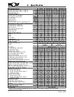
Page 10: ... 0 8 5 1 0 Pump pressure stage 2 bar 12 0 2 5 12 0 2 5 16 8 2 5 16 8 2 5 Maximum negative pressure in oil line bar 0 3 0 3 0 3 0 3 Flow temperature factory setting C 80 80 80 80 Max Flow temperature C 90 90 90 90 Heating water pressure drop at Δ T 20 K mbar 3 6 3 6 6 6 Heating water pressure drop at Δ T 10 K mbar 12 12 21 21 Max permissible boiler pressure bar 3 3 3 3 Heating surface heating water...

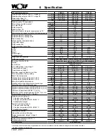
Page 11: ...r 16 8 2 5 16 8 2 5 23 5 2 5 Maximum negative pressure in oil line bar 0 3 0 3 0 3 Flow temperature factory setting C 80 80 80 Max Flow temperature C 90 90 90 Heating water pressure drop at Δ T 20 K mbar 17 17 54 Heating water pressure drop at Δ T 10 K mbar 55 55 205 Max permissible boiler pressure bar 3 3 3 Heating surface heating water heat exchanger m 3 05 3 05 3 85 Water capacity of the heat e...

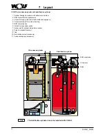
Page 12: ...linder heating 5 DHW circulation line 6 Protective magnesium anode 7 Sensor well for cylinder temperature sensor 8 Drain in standard delivery 9 Trap 10 Neutralising system accessory 11 Condensate pump accessory COB TS oil condensing boiler with stratification cylinder Cold water DHW DHW circulation Oil condensing boiler Stratification cylinder TS stratification cylinder cannot be installed with CO...

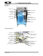
Page 13: ...ssure switch Drain valve Flame monitors Fan Regulated stratification pump Plate heat exchanger Immersion pipe cylinder sensor Stratification sensor Cylinder charging pump Heating return 1 Expansion vessel 8 l accessory Heating flow 1 DHW circulation pump accessory Drain Sacrificial anode under the cover Cold water connection optional accessory DHW connection COB component description Component des...

Page 14: ... bearing base is required for the installation of the boiler or the stratification cylinder to prevent air collection in the boiler and therefore system faults Level the boiler and stratification cylinder horizontally using adjustable feet Open flue oil condensing boilers must only be installed in a room which complies with the appropriate ventilation requirements Otherwise there is a risk of asph...

Page 15: ...ry set to 75 C and may be adjusted to 90 C if required In DHW mode the max flow temperature is factory set to 80 C and may be adjusted to 90 C if required It is only possible to refrain from using a minimum flow rate at temperatures lower than 80 C to prevent damage to the heat exchanger from overheating and steam knocking The return line to the appliance must have a dirt trap A sludge separator w...

Page 16: ...ted heating output1 conversion total hardness 1 mol m 5 6 dH 10 fH Total heating output VA 20 l kW VA 20 l kW and 50 l kW VA 50 l kW Total hardness total alkaline earths Conductivity2 at 25 C Total hardness total alkaline earths Conductivity2 at 25 C Total hardness total alkaline earths Conductivity2 at 25 C kW dH mol m C µS cm dH mol m C µS cm dH mol m C µS cm 1 50 16 8 3 0 800 11 2 2 800 0 113 0...

Page 17: ...the maximum rated heating output of the smallest heat source 2 High salinity 800 µS cm Low salinity 100 µS cm 3 0 11 dH recommended standard permissible up to limit of 1 dH System with a COB 20 system volume 800 l Total hardness of untreated potable water 18 dH VA 800 l 20 kW 40 l kW Because the specific System volume VA is between 20 and 50 l kW with a total output of 50 kW the fill and top up wa...

Page 18: ...e tube 6 flat packings 1 1 Pipe bend 2 flat packings 1 EPDM 1 Pump 1 adaptor fitting G1 fem 2 double nipples G 1 male G 1 on G1 male 1 elbow with air vent TS accessory set for cold water comprising 1 expansion vessel 8 l 1 cold water connection pipe to the expansion vessel 2 double nipples 1 trimming set Pipe assembly comprising 1 Circulation pump EE 0 2 2 thermometers in flow and return 2 ball va...

Page 19: ...flow Boiler return Cold water connection A maintenance valve must be installed in the cold water supply line If the pressure of the cold water supply is more than the maximum permitted operating pressure of 10 bar a tested and certified pressure reducer must be installed If mixer taps are used provide a centralised pressure reducer Observe the regulations of DIN 1988 as well as those of your local...

Page 20: ... demand once the installation has been filled 3 Set the ON OFF switch of the cylinder charging pump to Vent ON OFF switch Air vent valve 4 Set the cylinder charging pump to constant pressure again and start the cylinder 14 Cylinder connection Venting the heating circuit of the TS stratification cylinder ...

Page 21: ...r fixing to the corrugated stainless steel pipes of heating flow and return The safety assembly and the required pipe assembly can be installed on the left on the right or at the back of the boiler on a wall or attached to the side of the boiler casing Note The pipe assembly for three heating circuits should always be wall mounted Pipe assembly for three heating circuits with manifold for safety a...

Page 22: ... the oil pump the fuel oil must be supplied to the filter using a suitable manual pump The temperature must not fall below 5 C External tanks must have supplementary heating facilities The oil lines must be installed while the system is isolated from the electrical supply in order to avoid leaks Contaminants can lead to system damage The oil line must be flushed prior to commissioning The maximum ...

Page 23: ...oilpumpandthemotorplug Use low sulphur fuel oil to protect the environment 1 Permitted bio oil constituents The COB from date of manufacture May 2010 can be operated with fuel oil with up to 10 alternative constituents B10 to DIN V 51603 6 2 Bio oil quality The bio oil must comply with EN 14213 when the customer tank is filled 3 Oil storage tanks The customer must obtain written confirmation from ...

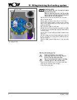
Page 24: ...ctors on the combustion chamber pan The sealing plugs located on the trap sealing plugs must be removed before assembly of the trap so that the condensate can freely flow through the trap Otherwise this leads to an operating fault With a flexible trap drain hose form a connection from to the on site drain with a continuous slope condensate drain level from trap 260 mm When using a condensate pump ...

Page 25: ...d flue should be installed with a slope of at least 3 6 cm m to the oil condensing boiler Fit spacer clips to secure the equipment in position In the worst case scenario a lesser slope of the air flue gas routing system may lead to corrosion or operating faults Always bevel or deburr trimmed flues to ensure gas tight installation of pipe joints Ensure that gaskets are fitted correctly Remove all c...

Page 26: ...mperature to position 2 pump running illuminated signal ring as status indicator constantly green Vent the pump for this briefly open and then retighten the air vent screw Vent the heating circuit completely switching the boiler ON for 5 sec and OFF for 5 seconds at the ON OFF switch five times in succession When the system pressure drops below 1 5 bar top up the water Note 19 Filling draining the...

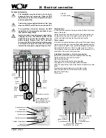
Page 27: ...Screw the strain relief into the holes provided Strip approx 70 mm off the power cable insulation Push the cable through the strain relief and tighten the strain relief Terminate the appropriate cores at the Rast 5 plug Push the inserts back into the terminal box casing Insert the Rast 5 plug Fit the cover Fuse M 5A Mains 230 V 50 Hz 2 wire eBus connection Replacement Fuse Outside sensor Cylinder ...

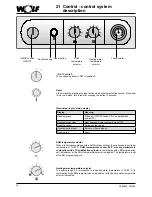
Page 28: ...ation with a BM programming unit adjustment at the heating water temperature selector is disabled DHW temperature selector When oil boilers are combined with a DHW cylinder setting 1 9 corresponds to a cylinder temperature of 15 65 C DHW temperatures of over 60 C are not permissible in conjunction with a TS stratification cylinder In combination with a BM programming unit adjustment at the DHW tem...

Page 29: ...at According to the pump operating mode the circulation pump operates constantly factory setting or only in parallel with the burner activation run on period Emissions test mode The emissions test mode is activated by rotating the heating water temperature selector into position The illuminated signal ring flashes yellow After the emissions test mode has been activated the boiler will heat with th...

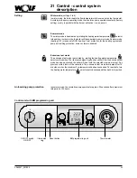
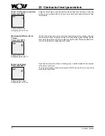
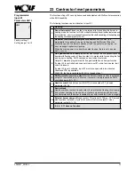
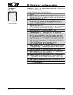
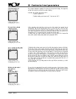
Page 30: ... to 20K 10K HG06 Pump operating mode 0 to 3 0 HG07 Boiler circuit pump run on time 0 to 30min 4 min HG08 Maximum limit boiler circuit TV max 40 to 90 C 75 C HG09 Burner cycle block 1 to 30 min 10 min HG13 Programmable input E1 1 to 11 1 HG14 Programmable output A1 0 to 14 0 HG15 Cylinder hysteresis 1 to 30K 5K HG16 N A HG17 N A HG19 Run on time cylinder charging pump 0 to 10 min 5 min HG20 Maximum...

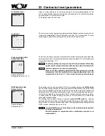
Page 31: ...y setting 0 Setting range 0 1 Contractor level Press r h rotary selector to in the 2nd to change to the 2nd programming level Turn the r h rotary selector clockwise to select the contractor level and confirm the selection by pressing the r h rotary selector again The display shows the code scan Contractor The correct code is set by pressing display indication flashes and then turning the r h rotar...

Page 32: ... 2 5 mol m the DHW temperature may be set to a maximum of 50 C If the total hardness is greater than 20 dH 3 58 mol m we recommend using a water treatment facility in the cold water supply line for DHW heating to prolong the maintenance interval descaling DHW heat exchanger Note 23 Contractor level parameters The burner switching differential regulates the burner temperature within a set range by ...

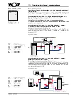
Page 33: ...ZUP MCP SPL Cylinder Low loss header or Buffer SF KF Pump operating mode 0 Heating circuit pump for heating systems without cascade control and without low loss header The heating circuit pump runs constantly when there is a heat demand The heating circuit pump will be switched OFF during cylinder heating if DHW priority has been selected Pumping operation type 1 HG13 1 without header sensor at th...

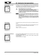
Page 34: ...has no function during cylinder heating and the boiler water temperature may also be higher during this time Reheating effects can result in the temperature being slightly exceeded Maximum limit Boiler circuit TV max Parameters HG08 HG08 75 Factory setting 75 C Setting range 40 to 90 C 23 Contractor level parameters Each time the burner is shut down in heating mode it will be disabled for the dura...

Page 35: ...ating contact Closed contact is a prerequisite for enabling the fan and burner in heating DHW cascade and emissions test mode Output A1 must be programmed for flue gas ventilation air damper function If output A1 is controlled and does not close input E1 within two minutes fault code 8 is issued If output A1 is not controlled input E1 must also open within two minutes Otherwise FC8 is generated Wi...

Page 36: ...fan starts The feedback is checked via input E1 If input E1 does not close the fan and burner will not start and after two minutes FC8 will be generated The flue gas ventilation air damper is controlled until the fan starts If input E1 is interrupted during burner operation the burner shuts down In case of a fault e g pressure switch flame failure during operation etc the flue gas damper is closed...

Page 37: ...s on the BM module The control unit reverts to heating mode and cycles in the selected rhythm HG20 between heating and cylinder heating mode regardless of whether the cylinder has reached its set temperature or not This function remains enabled even in parallel mode parameter A10 set to 1 It is only disabled if it is set to 0 Set this parameter to 0 in heating systems with a high DHW consumption e...

Page 38: ...emperature TK max Parameters HG22 Factory setting 80 C Setting range 50 to 90 C The control unit is equipped with an electronic boiler temperature controller which has an adjustable max off temperature max boiler temperature The burner is switched off if this temperature is exceeded The burner will restart when the boiler water temperature has fallen by as much as the burner switching differential...

Page 39: ...x COB 40 Rated heating output at 80 60 C kW 56 4 84 6 112 8 76 0 114 0 152 0 Rated heating output at 50 30 C kW 59 2 88 8 118 4 80 0 120 0 160 0 Rated heat input kW 58 0 87 0 116 0 77 6 116 4 155 2 Lowest output at 80 60 C stage 1 kW 18 5 25 3 Lowest heating output at 50 30 C stage 1 kW 19 6 26 8 Lowest output kW 19 0 26 0 Specification Setting the eBus address in cascade mode see also installatio...

Page 40: ...equent heating circuit The flow rate should therefore be set upstream of the low loss header via a line regulating valve or butterfly valve Hydraulic separation Instead of the low loss header a heat exchanger can be installed If pipes are used which are not impermeable to oxygen this is a requirement in any case Directly heated DHW cylinder A DHW cylinder is generally connected downstream of the s...

Page 41: ...inutes To prevent flue gas being drawn back through adjacent roof outlets where several flue outlets are arranged next to each other and boiler faults linked to this arrange the outlets at approximately the same height and with at least 600 mm between them The maximum permissible straight length for concentric balanced flue routing must not exceed 16 m with an internal diameter DN 80 125 or 21 m w...

Page 42: ... individual appliances and downstream of the last appliance does not exceed 2 m 325 m was assumed as the geodetic height If the conditions at the installation site are different an individual calculation is required Number 2 x COB 29 2 x COB 29 3 x COB 29 4 x COB 29 2 x COB 40 3 x COB 40 4 x COB 40 Installation Type B23 Flue internal diameter DN 110 DN160 DN160 DN160 DN160 DN160 DN160 Total flue g...

Page 43: ...ned a test mark The distance from the cleaning and inspection aperture in the duct channel to the front edge of the flue can be twice the diameter of the flue up to a maximum of 35 cm as long as cleaning and inspection do not take place at the outlet Flues in shafts should be designed at the outlet in such a way that no precipitation can enter the space between the flue and shaft and the secondary...

Page 44: ...ired if cleaning or inspection cannot be carried out from the roof Before commissioning the combustion system have the safe usability of the flue system confirmed by the local flue gas inspector in Germany check local regulations Installing the flue 26 16 23 24 25 26 27 33 37 37 37 37 38 32 26 35 34 2 32 26 35 34 2 32 26 35 34 2 32 26 35 34 2 36 1 Oil condensing boiler 2 Connection adaptor with te...

Page 45: ... operation Connect motor cable from the flue gas damper via an on site junction box with programmable output A1 see the chapter Wiring diagram cascade operation Fit the cover Continue with the chapters Flue gas damper tightness test and Commissioning Terminal box Electrical connection installation information In the delivered condition the terminal box is fitted to the back panel of the boiler If ...

Page 46: ...h servomotor Limit switch COB 15 20 29 40 Programmable output A1 230VAC 200VA Note Flue gas damper limit switch must be potential free Otherwise the COB control unit is be destroyed Note The contractor parameter HG13 E1 input must be set to 5 and HG14 A1 output must be set to 7 Otherwise the boilers do not change into heating mode Power supply 230 VAC 200 VA Flue gas damper wiring diagram Junction...

Page 47: ...selector è COB starts Operate the first COB for at least 5 minutes Check the CO2 content in the air connectors on all other appliances If the CO2 value exceeds 0 2 within 15 minutes the leak must be found and remedied Subsequently close all test apertures again When doing so ensure the caps are seated firmly Testing the first COB for tightness Turn the temperature selector for heating water on the...

Page 48: ... gas system presents a risk of poisoning or asphyxiation due to the escape of flue gases Fit casing Open the shut off valves in the flow and return Open oil shut off valves tank oil line filter Switch on the heating emergency stop switch Switch on the system ON OFF switch on the control unit Remove cap from l h test port inlet air Insert test probe 2 cm Turn the program selector switch on the BM m...

Page 49: ...flashes yellow Measure the CO2 content and compare it against the values given in the stage 2 table below If required alter the CO2 content with parameter HG00 Modifying the parameter HG00 has also adjusted the speed for stage 1 For checking purposes the boiler must be set to stage 1 Switch HG28 burner operating mode from 2 two stage to 1 single stage Measure the CO2 content and compare it against...

Page 50: ... boiler closed When correctly set the boiler should not exceed the maximum CO2 values in accordance with the table below Appliance closed COB 15 COB 20 COB 29 COB 40 CO2 max Stage 2 13 5 Stage 1 13 5 O2 min Stage 2 2 7 Stage 1 2 7 If the CO2 value increases too greatly the balanced flue must be checked Enter flue gas values such as CO2 content flue gas CO content and soot value in the commissionin...

Page 51: ...ure temperature and CO2 in the inlet air and enter the values in the commissioning report see the commissioning report chapter The flue is not gas tight if the CO2 content 0 2 rectify the leak Terminate the emissions test mode by turning the temperature selector back to its original position If emissions test mode is not reset manually the appliance switches back to the original operating mode aut...

Page 52: ...ing screw stage 2 Pressure regulating screw stage 2 Danfoss oil pump Suntec oil pump Adjust the CO2 value in the lower load stage 1 Press the reset button Set the heating water temperature selector to 8 Approx 2 min after the burner starts measure the CO2 content with the CO2 test equipment and compare it against the values given in the stage 1 table below If required amend the CO2 content with th...

Page 53: ...g energy efficient operation in the operating instructions After completing the work refit the casing cover and check the CO2 value with the boiler closed When correctly set the boiler should not exceed the maximum CO2 values in accordance with the table below Appliance closed COB 15 COB 20 COB 29 COB 40 CO2 max Stage 2 13 5 Stage 1 13 5 O2 min Stage 2 2 7 Stage 1 2 7 If the CO2 value increases to...

Page 54: ...s test Flue gas temperature gross Inlet air temperature Flue gas temperature net Carbon dioxide content CO2 or oxygen content O2 Carbon monoxide content CO Soot value __________________ tA C __________________ tL C __________________ tA tL C __________________ __________________ ppm __________________ 10 Casing fitted 12 Control parameters checked 11 System user instructed documentation handed ove...

Page 55: ...17 98 360 6 22305 29 4204 64 1078 99 349 5 21157 30 4028 65 1041 100 339 4 20075 31 3860 66 1005 101 330 3 19054 32 3701 67 971 102 320 2 18091 33 3549 68 938 103 311 1 17183 34 3403 69 906 104 302 0 16325 35 3265 70 876 105 294 1 15515 36 3133 71 846 106 285 2 14750 37 3007 72 818 107 277 3 14027 38 2887 73 791 108 270 4 13344 39 2772 74 765 109 262 5 12697 40 2662 75 740 110 255 6 12086 41 2558 ...

Page 56: ...0 65 70 75 80 Pressure drop on the heating Pressure drop COB 29 Pressure drop mbar Water volume l h 0 400 800 1200 1600 2000 2400 2800 3200 3600 4000 4400 4800 5200 5600 6000 0 10 20 30 40 50 60 70 80 90 100 110 120 130 140 150 160 160 170 180 190 200 210 Pressure drop on the heating Pressure drop COB 40 Pressure drop mbar Water volume l h COB 20 20K spread COB 20 10K spread COB 29 20K spread COB ...

Page 57: ...there is exposure to fire from outside there is a riskthatthefireandsmokearetransmittedtoother floors This again results in a risk of asphyxiation or severe to life threatening burns and poisoning No clearance is required between the concentric balanced flue and combustible materials or components as temperatures above 85 C will not occur at the rated heating output The electronic flue gas tempera...

Page 58: ...d with the accessories Connection types Boiler Type Appliance type 1 2 3 Operating mode Can be connected to Room unsealed Room sealed Moisture resistant chimney Balanced flue chimney Air flue gas routing Certified balanced flue Moisture resistant flue COB 15 20 29 40 B23 B33 C33x C43x C53 C53x C63x C83x C93x Yes Yes B33 B23 C83x C43x C33x C53x C93x C63x B23 C53x B33 1 Mark x indicates that all com...

Page 59: ...haft with minimum dimensions rigid or flexible with horizontal concentric connection pipe DN 60 110 vertical DN 60 Rigid DN 60 13 Flexible DN 60 9 C93x Vertical flue for installation in a shaft with minimum dimensions rigid or flexible with horizontal concentric connection pipe DN 80 125 vertical DN 80 or DN 83 Rigid DN 80 29 24 21 Flexible DN 83 27 21 17 C93x Vertical flue for installation in a s...

Page 60: ...gth m 10 8 12 14 16 18 20 22 24 26 28 30 32 120 130 140 150 160 170 COB 40 COB 29 COB 15 20 Flue DN80 COB 15 20 29 DN110 COB 40 5 7 9 11 13 15 100 110 120 130 140 150 160 Round duct Ø mm Flue DN60 COB 15 Rigid flue DN60 Flexible flue DN60 Max vertical length m Due to the required secondary ventilation in accordance with DIN 18160 when routing a balanced flue so that it is rigid and flexible in a d...

Page 61: ...1 Roof outlet external wall 23 support rail 24 87 support bend 25 Spacer 26 PP flue pipe 500 mm 1000 mm 2000 mm 27 Shaft cover 28 Air pipe 29 Air intake pipe 33 PP outlet Install the horizontal flue with a fall of approx 3 6 cm m towards the boiler Route the horizontal air supply with a 3 fall towards the outside install the air inlet with wind protection permissible wind pressure at the air inlet...

Page 62: ...liding socket if required 9 45 bend 10 87 inspection piece 11 Bend 87 12 Universal tile for pitched roof 25 45 13 20 50 Klöber adaptor 14 Flat roof collar Install the horizontal flue with a fall of approx 3 6 cm m towards the boiler When installing slide the separator 8 fully into the female connection Push the next balanced flue 4 50 mm dim S into the female connection of the separator and ensure...

Page 63: ...nspection port 33 PP outlet Install the balanced flue distributor 29 mm excentrically 29 for separate balanced flue on the oil condensing boiler Install the horizontal flue with a fall of approx 3 6 cm m towards the boiler Route the horizontal air supply with a 3 fall towards the outside install the air inlet with wind protection permissible wind pressure at the air inlet 90 Pa The burner will not...

Page 64: ...rox 100 mm longer than distance A Always trim the flue on the smooth side never on the female connection side Chamfer the flue with a file after trimming D istance A Offset 11 10 11 11 4 4 Distance A Distance A Bend Offset 87 Min 204 mm 45 Min 93 mm When installing slide the separator 8 fully into the female connection Push the next balanced flue 4 50 mm dim S into the female connection of the sep...

Page 65: ...ulting from incorrect pipe lengths excessive pressure drop premature wear with escaping flue gas and condensate or incorrect function e g through components working themselves loose are excluded from our warranty if third party equipment that is only CE DIBT certified is used Horizontal balanced flues must be no longer than 3 m when connecting the system to a combustion air supply and a separate f...

Page 66: ...230 V AC 50 Hz LP External primary pump 230 VAC E1 Programmable input eBUS BUS connection for external Control accessories KKP Boiler circuit pump AF Outside sensor SF Cylinder sensor Mains Accessories Charging pump Output A1 Heating circuit pump Stratification pump Oil pump N terminal Ignition Oil preheating L valves Valve 1 Valve 2 Input E1 Outside sensor PWM stratification pump Stratification s...

Page 67: ... and hold down the reset button on the standard control unit whilst setting the ON OFF switch to I ON Hold down the reset button again for at least 2 seconds after switching on the system All parameters individual settings are returned to their factory settings by a reset 0 I 0 C 20 40 60 80 100 120 ON OFF switch Reset button ...

Page 68: ...flue system for leaks service required 6 Temperature limiter excess temperature The flow has exceeded the limit of the temperature limiter 100 C Vent the system check the heating circuit pump 7 Flue gas sensor excess temperature The flue gas temperature has exceeded 120 C Clean the heat exchanger Check whether all displacement devices are installed check the flow through the boiler Check if flow a...

Page 69: ...fuse 52 Max Cylinder heating time exceeded Set cylinder temperature has not been reached sufficient flow Vent cylinder increase cylinder heating time HG20 check cylinder sensor installation 78 Header sensor fault Faulty header sensor or lead Check sensor and lead Insufficient heating system heating frequent cycling Air in the heating or cylinder system Vent radiators vent cylinder primary circuit ...

Page 70: ...Seasonal space heating energy efficiency ηs 91 91 91 92 Annual energy consumption for space heating QHE 8396 11209 16571 21913 Sound power level indoors LWA dB 56 60 60 60 Any specific precautions that shall be taken when the space heater is assembled installed or maintained See installation instruction See installation instruction See installation instruction See installation instruction Wolf Gmb...

Page 71: ...15 Annual energy consumption for space heating QHE 8396 8396 8396 8396 Annual fuel consumption for water heating AFC GJ 17 18 18 23 Seasonal space heating energy efficiency ηs 91 91 91 91 Seasonal water heating energy efficiency ηwh 83 81 81 80 Sound power level indoors LWA dB 56 56 56 56 Any specific precautions that shall be taken when the space heater is assembled installed or maintained See in...

Page 72: ... be taken when the space heater is assembled installed or maintained See installation instruction See installation instruction See installation instruction See installation instruction Supplier s name or trade mark Wolf GmbH Wolf GmbH Supplier s model identifier COB 20 SEM 1 750 COB 20 SEM 1 1000 Load profile XXL XXL Seasonal space heating energy efficiency class A A Water heating energy efficienc...

Page 73: ... be taken when the space heater is assembled installed or maintained See installation instruction See installation instruction See installation instruction See installation instruction Supplier s name or trade mark Wolf GmbH Wolf GmbH Supplier s model identifier COB 29 SEM 1 750 COB 29 SEM 1 1000 Load profile XXL XXL Seasonal space heating energy efficiency class A A Water heating energy efficienc...

Page 74: ...60 60 60 Any specific precautions that shall be taken when the space heater is assembled installed or maintained See installation instruction See installation instruction See installation instruction See installation instruction Supplier s name or trade mark Wolf GmbH Name COB 40 SEM 1 1000 Load profile XXL Seasonal space heating energy efficiency class A Water heating energy efficiency class B Ra...

Page 75: ...003 0 003 0 003 0 003 Seasonal central heating efficiency ns 91 91 91 91 91 91 92 Efficiency at rated heating output and high temperature operation n4 91 2 91 2 91 6 91 6 91 1 91 1 91 9 Efficiency at 30 of rated heating output and low temperature operation n1 97 3 97 3 96 8 96 8 97 1 97 1 97 5 Heat loss on standby Pstby kW 0 068 0 068 0 091 0 091 0 099 0 099 0 107 Energy consumption of ignition fl...

Page 76: ...07 DIN EN 15035 05 2007 DIN EN 12828 06 2003 DIN EN 61000 3 2 2015 EN 61000 3 2 2014 DIN EN 61000 3 3 2014 EN 61000 3 3 2013 DIN EN 55014 1 2012 EN 55014 1 2006 A1 2009 A2 2011 DIN EN 55014 2 2016 EN 55014 2 2015 DIN EN 60335 1 2014 EN 60335 1 2012 AC 2014 DIN EN 60335 2 102 2016 EN 60335 2 102 2016 In accordance with the following Directives 92 42 EEC Efficiency Directive 2014 30 EU EMC Directive...

Page 77: ...H Address Industriestrasse 1 D 84048 Mainburg Product TS cylinder The product described above conforms to the requirements specified in the following documents DIN EN 12897 2006 09 In accordance with the following Directives 2009 125 EC ErP Directive this product is identified as follows 42 Declaration of Conformity Jörn Friedrichs Head of Development ...

Page 78: ...78 3062547_201802 43 Notes ...

Page 79: ...79 3062547_201802 43 Notes ...

Page 80: ...WOLF GMBH POSTFACH 1380 D 84048 MAINBURG TEL 49 0 87 51 74 0 FAX 49 0 87 51 74 16 00 www WOLF eu Doc no 3062547_201802 Subject to technical modifications ...

Reviews: