36
3062815_0110
16. Flat roof installation
For example, concrete ties can be placed on the flat roof and the support frames
can be affixed to them. The required weight of the concrete ties depends on
the wind energy that increases with the height of the building.
Also, the wind energy at the roof edge is stronger than at the centre of the roof.
Consequently, the distance from the collectors to the edge of the building should
be greater than 1 m, not least to make the installation easier.
Should this weight exceed the permissible roof loading, secure the collectors
with at least 100 kg per collector against slippage and apply a guy wire of at
least 4 mm Ø as security against tipping over.
As an alternative to applying weights, a (steel) substructure can also be used. For
this, at least 2 rows are interconnected. This creates favourable lever conditions
that prevent the collector weight tipping over. In addition the substructure creates
the benefit that uneven surfaces can be levelled out.
Unsecured support frames can be pushed over and damaged by the force of
the wind. Therefore secure the collectors on the roof. First check the static
suitability of the sub-structure and the permissible area loading for the roof skin
(if necessary call on the services of a structural engineer).
Weights can be used as ballast to protect the roof skin from damage
(drilling).
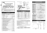
Fixing information
Minimum clearance between
several rows of collectors
(angle of shade = 17°)
Wind
Wind energy
Ballast (weights)
Selection of hole
size
Fit the diagonal leg to the respective hole in the vertical
leg, subject to the required angle.
Mark the vertical leg above the diagonal leg and trim
to size (see diagram).
45°
30°
20°
2.06
m for on end installation
Height of
building
Area exposed to
wind
Wind energy Fw
Required ballast
per collector
0 – 8 m
2.30 m
2
2030 N
175 kg
8 – 20 m
2.30 m
2
2800 N
295 kg
> 20 m
2.30 m
2
Requires an individual calculation to
DIN 1055-4
Minimum clearance and angle for the supports when installing the collector on end
(example: Würzburg)
Angle of inclination
β
Hole dimension
"h" (cm)
Hole dimension
"d1" (cm)
Clearance dimension
"d" (cm)
30
117 (
available
)
333
507
45
- (
available
)
471
613


