


8 21 06 8:
M PE G -3 27 0 & 42 9 0 U se r G u id e
© 20 13 Wo hl e r Te c hn ol og i e s , In c . A l l r ig h ts re se rv ed .
35
C h a p t er 4
Configuration
M a r k er M e n u
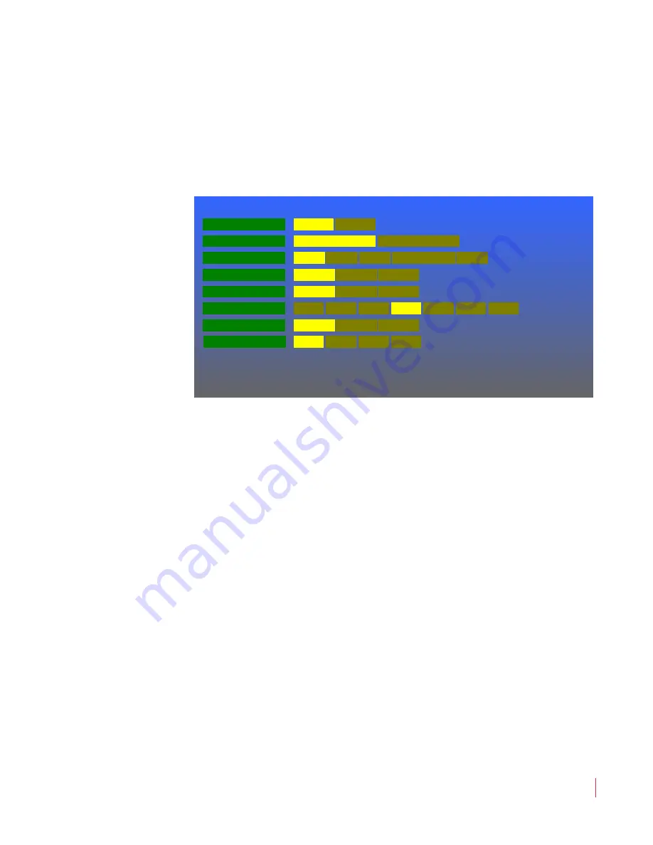
Marker Menu
This menu defines if and how markers will appear on the screen. The
Marker Menu
is shown in
Figure 4–5
.
Figure 4–5
Marker Menu
Rotate the
Volume
knob to highlight the item to be adjusted, and then
press to enter it. Again rotate the
Volume
knob to the option selection
and press to choose it:
1.
Marker Enable (All)
: Selecting
On
causes any markers set up in
this menu to appear on the screen. Selecting
Off
will not allow any
markers to display. The default is
Off
.
2.
Marker Background
: By default the
Normal
choice is selected,
which means that the background is transparent, allowing the
video to display normally.
Matte
represents a future feature.
3.
Marker Color
: The color of the markers can be one of six choices.
By default the
White
choice is selected.
4.
Center Marker
: The center marker may be turned
On
or
Off
.
Selecting
GPI
control will allow an external GPI input, as set in the
GPI-In Menu on page 39
, to select whether the
Center Marker
appears or not. The default is
Off
.
5.
Area Marker
: The area marker may be turned
On
or
Off
. The
aspect ratio of the
Area Marker
is as selected in the
Area Ratio
option in this menu. Selecting
GPI
control will allow an external
Marker Enable (All)
Marker Menu
Marker Background
Marker Color
Center Marker
Area R atio
Normal
Matte
W hite
Green
Blue
Yellow
Gray
Off
4 :3
13 :9
14:9
16:9
1.85:1
2.35:1
32 :9
R ed
On
Safety Marker Size
80%
85 %
90 %
95%
Area Marker
O ff
On
G PI
G PI
Safety Marker
O ff
On
G PI
O ff
On


