


8 21 06 8:
M PE G -3 27 0 & 42 9 0 U se r G u id e
© 20 13 Wo hl e r Te c hn ol og i e s , In c . A l l r ig h ts re se rv ed .
15
C h a p t er 2
Quick Start
Se t t i n g up I n p u t s
4.
After connecting the power cords, you should see the A and B
indicators below each screen light up. Press the
Power
button
located at the left under each screen.
5.
For 30 seconds, the
Power
indicators should flash. Then the
screens should show a progress bar, followed by some white
flashes and a splash screen showing the MPEG Series product line.
The start up process takes just over a minute. When the start up
process is complete, you should see the words, “SDI-A: No Sync”
at the upper left of the screen, assuming that no SDI signal is in fact
present.
6.
Proceed to
Monitoring a 3G/HD-SDI Signal on page 15
,
Monitoring an ASI Stream on page 16
,
Monitoring an Ethernet
Stream on page 18
, or
Monitoring an HDMI Signal on page 19
,
depending upon your monitoring needs.
Setting up Inputs
Monitoring a 3G/HD-SDI Signal
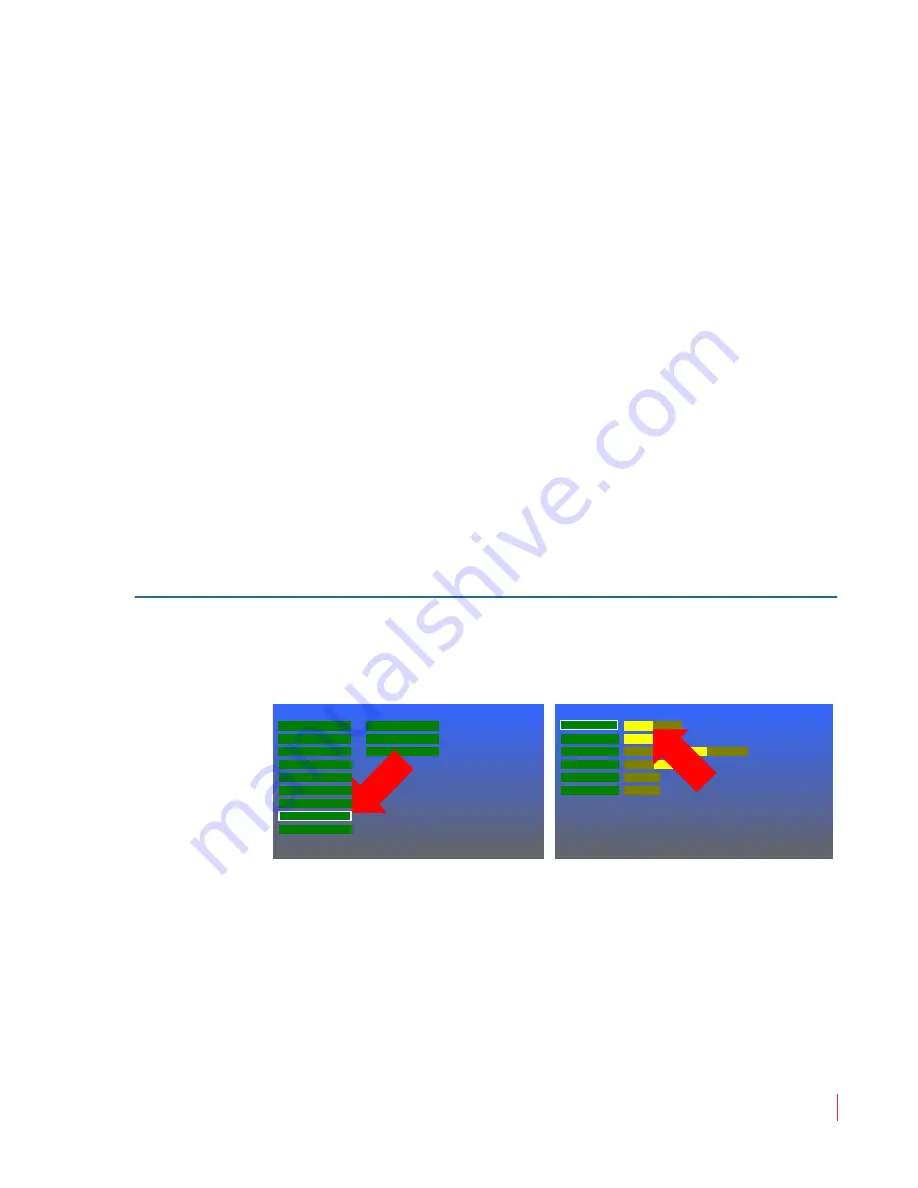
1.
Press the
Menu
button to open the
Main Menu
. Rotate the
Volume
knob to highlight the
System Menu
selection and press
it to enter the
System Menu
.
2.
The
SDI
option should already be selected by default on
BNC
Ports A
&
B
. If it is not set this way, it can be changed by pressing
the
Volume
knob once and then turning it to move the selector on
BNC
Port A
to
SDI
. Press the
Volume
knob once to select
SDI
.
Use the same process for
BNC Port B
if you intend to connect an
SDI signal to
SDI/ASI Input B
. Finally press the
Menu
button
twice to exit.
Video Menu
Main Menu
Audio Menu
Marker Menu
Functions Menu
OSD Menu
System Menu
Preset Menu
System Status
GPI-In Menu
Network Menu
MPEG Status
UMD Options Menu
BNC Port B
System Menu
Backlight Interval
Panel LEDs
Calibration
Upgrade
None
5m
4h
8h
24h
48h
Restore
Upgrade
SDI
ASI
Off
On
BNC Port A
SDI
ASI


