The Measure of Technology
Manual
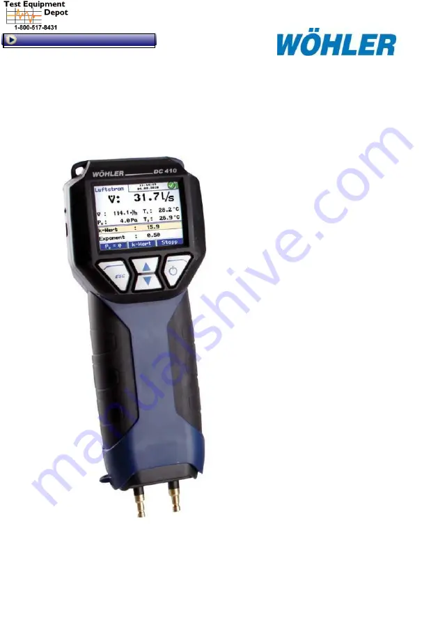
Pressure Differential and Flowmeter
A
rt.
n
°.
2
2
6
2
7
–
2
0
1
2
-08
-26
Wöhler DC 410
FLOW
99 Washington Street
Melrose, MA 02176
Phone
781-665-
1400
Toll Free 1-800-517-8431
Visit us at www.T
estEquipmentDepot.com


