background image


10

Conveyor Belt Tracking 

 
Belt tracking adjustment may be necessary 
during the break-in period to compensate for belt 
stretching. 
 
Abrasive belt tension must be properly adjusted 
before adjusting the tracking. Adjust the belt 
tracking while the conveyor belt is running at its 
fastest speed.   
 
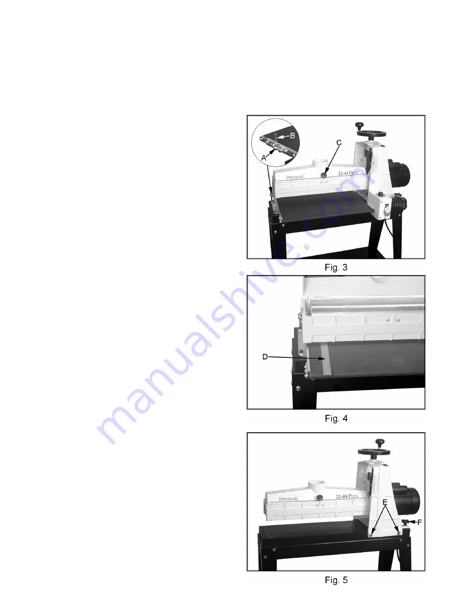
Tighten the hex nut (Fig. 3, Item A) on the side 
the belt is drifting towards, and loosen the hex 
nut on the opposite side. Use the attached 
wrenches (Fig. 3, Item B) to adjust the hex nuts. 

Note:

 Adjustment should be made in 1/4 turns of 

the hex nut. Allow time for the belt to react to the 
adjustment. Do not over adjust. 
 

Dust Cover 

 
To open the dust cover, push in on the knob 
(Fig. 3, Item C) and lift. 
 

Checking Drum Alignment


The sanding drum comes preset from the 
factory. If a problem with the drum alignment 
occurs follow the instructions listed below. 
 
1.  Push in and lift the knob (Fig. 3, Item C) to 

open the cover and remove the abrasive 
strip. If you are unsure how to do this, see 
the “Wrapping Abrasive Strips” section in 
this manual. 

 
2.  Using a metal straight edge, or ruler, as a 

thickness gauge (Fig. 4, Item D), insert the 
gauge between the drum and the conveyor 
bed on the outer end of the drum. 

 
3.  Open the dust cover and lower the sanding 

drum while slowly rotating the drum by hand 
until the drum lightly contacts the thickness 
gauge. 

 
4.  Remove the thickness gauge and place it 

under the drum at the opposite end. If the 
drum does not contact the thickness gauge 
to the same degree as the other end of the 
drum, alignment is necessary. 


Aligning the Drum 

 
1.  Loosen the four hex cap bolts (Fig. 5, Item 

E) (two in front and two in back). 

 
2.  Lay the thickness gauge under the drum 

lengthwise. 


3.  Adjust the knob, (Fig. 5, Item F) until the 

drum contacts the gauge equally along its 
entire surface. Turn the adjusting knob 
clockwise to raise the outboard end of the 
drum, and counterclockwise to lower the 
outboard end of the drum. 

 
4.  When the drum is parallel to the conveyor, 

tighten the four hex cap bolts. 


Summary of Contents for PERFORMAX 22-44 Plus

Page 1: ...22 44 Plus Drum Sander shown with optional accessories WMH TOOL GROUP 2420 Vantage Drive Elgin IL 60123 Phone 888 594 5866 Part No M 649003K Fax 800 626 9676 Revision B www wmhtoolgroup com Copyright...

Page 2: ...utside our facilities or to a lack of maintenance WMH TOOL GROUP LIMITS ALL IMPLIED WARRANTIES TO THE PERIOD SPECIFIED ABOVE BEGINNING FROM THE DATE THE PRODUCT WAS PURCHASED AT RETAIL EXCEPT AS STATE...

Page 3: ...3 Setting the Depth of Cut 13 Establishing the Proper Drum Height 13 Selecting SANDSMART Feed Rates 14 Abrasives 14 Selecting Drum Abrasives 14 Selecting Abrasive Grits 15 Stock Feeding Angle 15 Multi...

Page 4: ...y equipment such as face or dust masks that are specifically designed to filter out microscopic particles 11 Do not operate this sander while tired or under the influence of drugs alcohol or any medic...

Page 5: ...ne tipped or if the sanding drum is unintentionally contacted 35 Never leave the machine running unattended Turn the power off and don t leave the machine until it comes to a complete stop 36 All door...

Page 6: ...up WMH Tool Group can also be reached at our web site www wmhtoolgroup com Specifications Stock Number 649003K Max Width in 44 two passes Min Length in 2 1 4 Max Thickness in 4 Min Thickness in 1 32 D...

Page 7: ...les that accept the tool s plug Repair or replace a damaged or worn cord immediately 115 Volt Operation As received from the factory your sander is ready to run at 115 volt operation This sander when...

Page 8: ...er 1 Set of Open End Wrenches 1 Set of Allen Wrenches 1 Adjustable Wrench Read and understand the entire contents of this manual before attempting assembly or operation of this drum sander Failure to...

Page 9: ...is controlled by the height adjustment handle Fig 2 Item B Turning the handwheel in a counterclockwise direction lowers the drum Turning the height adjustment handwheel one revolution lowers the drum...

Page 10: ...n the cover and remove the abrasive strip If you are unsure how to do this see the Wrapping Abrasive Strips section in this manual 2 Using a metal straight edge or ruler as a thickness gauge Fig 4 Ite...

Page 11: ...djusting knob clockwise to raise the outboard end of the drum and counterclockwise to lower it Tighten the four hex cap bolts Repeat this process until the ridge is gone and the entire board is sanded...

Page 12: ...through the slot into the take up fastener Position the abrasive strip with sufficient room between the inside of the slot and the tapered end of the strip to allow it to be pulled into the drum as n...

Page 13: ...the most important set up procedure before operating the sander It may take some experimentation to determine the proper depth of cut given the variables of abrasive grit and types of wood For best re...

Page 14: ...ing the conveyor and or decreasing the depth of cut and run the stock through again Abrasives The abrasive material you choose will have a substantial effect on the performance of your sander Variatio...

Page 15: ...e same thickness Edge Sanding When edge sanding the Performax sander will mimic the opposite edge of the stock which is lying on the conveyor belt Because of this it is important for the stock edge to...

Page 16: ...hing Abrasive Life Abrasive life can also be increased by removing the abrasive strip from the drum and reversing it To do this remove the strip and use what was the trailing end as the starting end o...

Page 17: ...4 Lower the sanding drum so that it just touches the conveyor bed 5 Turn the drum height handle one complete revolution to raise the drum 6 Retighten the bearing hex nuts Tension Roller Pressure Adjus...

Page 18: ...duce the depth of cut 3 Use a coarser grit or reduce the depth of cut 4 Increase the feed rate 5 Clean the abrasives 6 Replace the abrasives Board slips on conveyor belt 1 Tension rollers are too high...

Page 19: ...19 Drum Head Assembly...

Page 20: ...04 Set Screw 1 4 20x1 4 4 25 50 2209 Spider Coupling 1 26 80 3138 Knob Fine Tune Adjustment 1 27 TS 0060081 Hex Head Cap Screw 3 8 16x1 3 4 1 28 20 3216 Spring 1 29 30 9022 Base Conveyor Mounting 1 3...

Page 21: ...21 56 11 1000 04 Washer Lock Int Tooth 1 4 2 57 12 2000 04 Hex Nut 1 4 20 2 58 11 1002 04 Flat Washer 1 4 2 59 12 9001 Hex Nut Nylon Insert Lock 6 32 2 60 2244PLUS 260 Hex Nut 3 8 16 1...

Page 22: ...22 Conveyor and Motor Assembly...

Page 23: ...19 72 2004 Switch ON OFF Drum 1 20 30 0122 Coupler Shaft 1 21 10 4010 04 Set Screw 1 4 20x1 4 2 22 40 4903 Bracket Base Controller 1 23 40 4022W Cover Base Control Housing 1 24 10 4004 12 Bolt Hex Wa...

Page 24: ...24 Wiring Diagram...

Page 25: ...25 WMH Tool Group 2420 Vantage Drive Elgin IL 60123 Phone 888 594 5866 Fax 800 626 9676 www wmhtoolgroup com...

Reviews: