background image

12 

Translation of the original operation manual Airless


Phoenix_BAoDB_en_1210 

 jw

Installation and Assembly

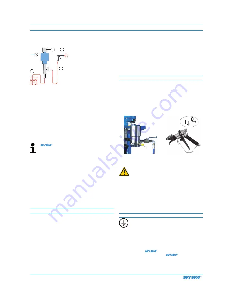
1  Airless unit

2  Airless spray gun

3  Paint container

4  Spray hose

Picure 4.1

1

2

3

4

Job

The unit is to be installed at the job site and prepared for 

operation.


Prerequisite


The material to be worked with is prepared.


All materials to be sprayed should be marked with 

information on viscosity, processing temperatures, 

mixing proportions etc. If this is not the case, please 

acquire this data from the relevant manufacturer.


The material to be sprayed must be slowly but tho-

roughly stirred before beginning to work.

 offers a broad selection of accesso-

ries for the optimised preparation of spraying 

materials, i.e.:


agitators in various sizes


material pre-heating containers in various 

sizes


fluid hester


If working with plural component materials, 

the pot life must be observed. 


To insure that the necessary volume of air is supplied, 

the compressor capacity must comply with the air con-

sumption requirements of the pump. 

The diameter of the air supply hoses must correspond 

to the connection on the pump.

1.  Set up the pump


The pump must be set up securely on a level and solid 

surface


Pay attention to the information covering the required 

floor space found in machin card. 


Operating elements must be easily accessible


Safety features must be 

easily accessible

Wall-mounted versions:


To fix the wall-mount, use M 12 screws - class 8.8


Be sure to use anchoring devices in accordance with 

the nature of the wall being used 


Ensure that at least 10 cm (4 in.) free space is left 

between the suction elbow and the floor after mounting 

(refer to the picture in Chapter 3) 


2.  Mount accessories

For transport purposes the following components were 

dismounted and packed in a separate carton:

1. 

Spray hose (Picture 4.2)

2. 

Airless spray gun (Picture 4.3)

3. 

Air regulator or maintenance unit (depending upon 

version)


Attach these items according to Picture 4.2 + 4.3. 

Note:

 The air maintenance unit is connected to the air 

inlet of the air motor.

Picture 4.2 Spray hose con

-

nection on the high-pressure 

filter

Picture 4.3 Spray hose con

-

nection to the spray gun

m

Warning!

Material leaks at connections can lead to se-

rious injury of property damage.

Check all turnable parts, nuts, screws and 

hose connections and tighten them securely.


Check the permissible maximum air pressure for the 

spray hose, spray gun and accessories. It must be 

greater than or equal to the maximum operational 

pressure shown on the pump's nameplate or on the 

machine card.

3  Ground the unit

Warning! 

Due to the high flow speed created by Airless 

equipment, static charging can occur. A static 

charge can lead to fires or explosion

A static charge can lead to fires or explosion. 


The pump and object to be coated must be 

grounded properly 


Only use conductive hoses 


Note: 

 spray hoses are conductive 

and compatible with 

 pumps

Summary of Contents for PHOENIX 11018

Page 1: ...Translation of original operation manual WIWA Phoenix Phoenix DBE en 02 12 jw Operation manual WIWA PHOENIX Type 6530 6552 11018 11032 Serial No Airless Air Combi Hot Job...

Page 2: ...ibited to pass on this operating manual for reproduction utili sation or communication of its contents unless this has been explicitly permitted Infringements incur an obligation to pay damage compens...

Page 3: ...corresponds with the present standards of technical regulations and current rules for accident prevention Picture 2 2 1 Picture 2 2 2 2 Safety 2 1 Description of symbols The signs and symbols used in...

Page 4: ...nts or lacqures that contain them are to be used we recommend contacting Customer Service or the factory directly for further information Please note that there are stainless steel Airless pumps that...

Page 5: ...be ensured that the pump is grounded separately or together with the equipment it is mounted to maximum resistance 106 picture 2 4 1 ground potential equalization Equipment that is not rated as explo...

Page 6: ...e this equip ment The management in charge of the operation of the machi ne must make the User s Handbook available to the ope rator and must make sure that he has read and unders tood it Only then ma...

Page 7: ...ications The unit must have a fixed position and sufficient space to ensure safe operating Keep the area you are working in clean especially walkways Remove any spilled paint or solvent imme diately E...

Page 8: ...aterials When handling auxillary materials such as paint solvent oil grease and other chemical substances comply with the safety and dosing instructions of the manufacturer and the generally applicabl...

Page 9: ...under or near the unit when it is suspen ded Serious injury could result Only use appropriate hoisting equipment with sufficient load capacity Secure the unit to the transporting vehicle in such a way...

Page 10: ...2 air motor 3 air pressure regulator with air tap lock and compres sed air connection nipple 4 vent hole 5 high pressure filter 6 material pump 7 suction pipe with strainer Phoenix Air Combi cart ver...

Page 11: ...tures must be easily accessible Wall mounted versions To fix the wall mount use M 12 screws class 8 8 Be sure to use anchoring devices in accordance with the nature of the wall being used Ensure that...

Page 12: ...the first time the sealing plug is to be removed from the venti lation hole overflow The ventilation hole is located in the elbow with the openeing facing downward picture 4 4 Pos 1 5 Check the releas...

Page 13: ...r tap lock 2 air pressure regulator 3 air connection 5 Clean the high pressure filter Hold the drain hose Picture 5 1 3 Pos 2 into the container B and secure against slipping Open the drain valve Pict...

Page 14: ...l knob counterc lockwise until the pump only runs very slowly Remove the suction pipe from the container A Funnel mounted versions Pump the solvent out of the funnel until it is empty Hold the spray g...

Page 15: ...h excessive material consumption and spray fog will result If the pressure is too low fingering and un even coating thicknesses will result 6 1 Equipment preparation Job Prepare the unit for operation...

Page 16: ...ge will be uneven and spotted Picture 6 2 1 The sprayer s arm must move evenly back and forth An even speed must be maintained Move the spray gun parallel to the surface being coated Move the spray gu...

Page 17: ...ightly Hold the spray gun against the inner wall of container B Trigger the gun until clean solvent is emitted Be sure to maintain contact with the inner wall of the container Close the spray gun and...

Page 18: ...8 1 Air Combi 1 Air Combi unit 2 Air Combi spray gun 3 Paint container 4 Spray hose 5 Air hose Picture 8 1 1 2 3 1 4 5 With this method the material being sprayed is fed to the air assisted airless Ai...

Page 19: ...d follow all instructions for start up Chapter 5 for normal operation Chapter 6 for shutting down Chapter 7 found in the separate User s Handbook for the fluid heater If residue solvent in the fluid h...

Page 20: ...ions of backpressure regulator Max operating pressure 400bar 5800psi Pressure adjustment range 0 400bar Operating temperature range 4 5 100 C Max output 13 3l min 3 5gal min Cleaning and depressurizin...

Page 21: ...lass Check regularly the release agent for discoloration caused by contact with the spray material The discoloration can be monitored by draining a small amount of release agent After checking add a c...

Page 22: ...of the motor In case of icing only use pure anti freezing agent Briefly trigger the spray gun To drain pressure open the drain valve screw on the high pressure filter Disassemble the high pressure fi...

Page 23: ...may not be operated without oil The maximum oil level is marked with a line around the reservoir To fill the reservoir remove the filler screw or remove the reservoir and fill directly Only use the re...

Page 24: ...Air supply pressure is too low 2 Tip new is too big 3 Tip is worn too big 4 Air motor is frozen runs too slow 1 Increase the inbound air pressure with the regulator and check the diameter of the inbo...

Page 25: ...material hose NW6 1 4 Airless tip Air Combi units Air Combi finishing gun Order No 0632578 including tip air and fluid hose NW 6 1 4 Hot Job units Spray Accessory Kit No 16 N R Order No 0642477 No 17...

Reviews: