background image

10 

Translation of the original operation manual 

HERKULES PFP  


HERKULES PFP_BAoDB_en_1402_B · rs

Safety

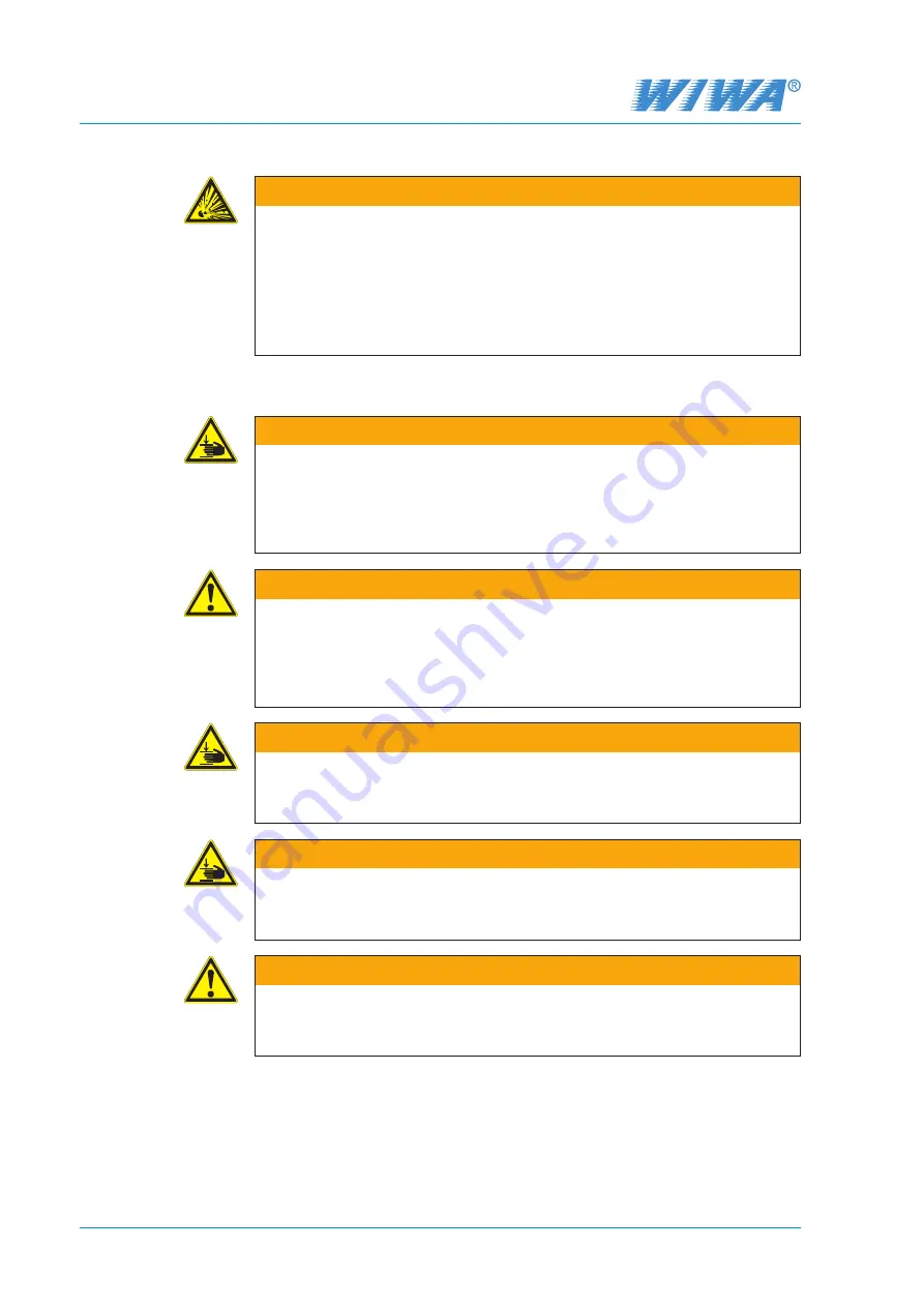
WARNING
Heating up cleaning agents can cause an explosion. This may result in seri-

ous injury to persons and damage to property.


Pay attention to the flashpoint and the ignition temperature of the clean

-

ing agent.


Switch off the material flow heater if you need to perform the following 

work: Cleaning, pressure testing, decommissioning, maintenance and 

repair.

2.2.5  Risks due to the rams

WARNING

While the rams are lifting, the moving components can crush your fingers, 

hands or other parts of the body.


Do not reach between the follow plate and the material drum, the tra-

verse and cylinder cover of the pneumatic cylinder or the clamping piece 

and the cylinder cover of the pneumatic cylinder.

WARNING
While the rams are lifting, loose clothing can get between the follow plate or 

the follow cover and the material drum or catch on other moving components 

or be pulled upwards.


Wear tight-fitting working clothes that are not very tear-resistant, that 

have tight-fitting sleeves and no protruding parts.

WARNING
While the rams are lifting, the moving components can cause crushing or 

impact injuries.


While the rams are lifting, nobody must be in the lifting area.

WARNING
Accidental starting of the rams can result in crushing and impact injuries.


Each time work is interrupted, set the ram control levers to the “Stop” 

position.

WARNING
Objects placed on the rams may fall down during a stroke movement and 

cause injuries.


Never place any objects on the rams!

Summary of Contents for HERKULES PFP

Page 1: ...Translation of the original operation manual HERKULES PFP_DBK_en_1402 rs Operation manual HERKULES PFP Serial No...

Page 2: ......

Page 3: ...nding wheels 13 2 4 4 Grounding cable 13 2 5 Operating and maintenance personnel 14 2 5 1 Unit owner s duties 14 2 5 2 Personnel qualification 14 2 5 3 Authorized operating personnel 14 2 5 4 Personal...

Page 4: ...2 3 Changing material drum 28 5 2 4 Intermediate flushing 29 5 3 Decommissioning 30 5 3 1 Complete flushing 30 5 3 2 Disassembling and cleaning the fluid pump 30 5 3 3 Assembling the fluid pump 32 5 4...

Page 5: ...commend adding all relevant guidelines and accident prevention instructions to this operation manual Moreover the manufacturer s instructions and guidelines for coating or feeder materials must be res...

Page 6: ...et up commissioning operation maintenance repair and servicing of the unit must have read and understood the operation manual beforehand especially the chapter entitled Safety Your safety is at stake...

Page 7: ...y spraying material or gases Use eye protection Indicates the requirement to wear protective goggles to protect against eye injuries caused by gases fumes or dust Wear ear defenders Indicates the requ...

Page 8: ...one to be taken as the maximum operating pressure for the entire unit Material hoses and hose assemblies must comply with the maximum operating pressure including the required safety factor Material h...

Page 9: ...sed in workshops that come under the explosion protection ordinance Explosion protected units meet the explosion protection requirements of Di rective 94 9 EC for the explosion group unit category and...

Page 10: ...and cylinder cover of the pneumatic cylinder or the clamping piece and the cylinder cover of the pneumatic cylinder WARNING While the rams are lifting loose clothing can get between the follow plate o...

Page 11: ...In closed or pressurized systems dangerous chemical reactions may occur if parts made of aluminium or galvanized parts come into contact with 1 1 1 tri chloroethane methylene chloride or other solvent...

Page 12: ...Function of compressed air shut off valves correct 5 5 Lead seal on the safety valves still intact 5 5 Safety valves externally free of damage 5 5 Grounding wheel clean and free of damag 5 5 Groundin...

Page 13: ...safety valve needs to be replaced you can find the corresponding order number on the machine card With new safety valves ensure that they have been set to the maximum permissible air inlet pressure of...

Page 14: ...structed by the unit owner in the activities they are tasked with and the potential risks connected with them in the case of incorrect behaviour Trained personnel have been instructed by the unit buil...

Page 15: ...burn injuries Wear protective footwear Wear protective footwear to prevent injuries to the feet due to objects that may fall drop or roll around and to prevent slipping on a slippery floor 2 6 Notes...

Page 16: ...Leakages WARNING In case of leakages material can escape under very high pressure and cause serious bodily injuries and material damage Immediately shut down the unit and depressurize it Retighten an...

Page 17: ...The technical data for your unit can be found in the attached machine card 3 1 Intended use The HERKULES PFP is intended for the application of insulating layer forming flame retardants in commercial...

Page 18: ...8 No Designation 1 Silencer 2 Air motor 3 Overflow with ventilation hole 4 Twin post ram 5 Fluid pump 6 Connection for the spray hose 7 Drain ball valve 8 Drain hose 9 Follow plate 10 Release agent fi...

Page 19: ...s 18 Air pressure regulator for the ram 19 Air pressure regulator for the pump 20 Deicing system 21 Pressure gauge for the air inlet pressure 22 Compressed air shut off valve 23 Compressed air connect...

Page 20: ...on the transport vehicle against slipping and falling off If the unit was already operated please observe the following Disconnect the entire system power supply even for short transportation distance...

Page 21: ...ld be extracted Protect objects adjacent to the spraying object against possible damage caused by the material mist 4 3 Assembly WARNING If assembly work is carried out by people who have not been tra...

Page 22: ...pump see Fig 9 Connect the spray hose to the spray gun as described in the operating manual for the spray gun Fig 9 Connection for the spray hose 4 3 3 Grounding the unit WARNING The high flow veloci...

Page 23: ...ers of the air supply hoses must match the connections such that an adequate air supply is ensured Operation with contaminated or moist compressed air causes damage to the unit s pneumatic system Use...

Page 24: ...ed protec tive equipment For details refer to chapter 2 5 4 on page 14 The material to be processed must be available in sufficient quantity In ad dition you will need one suitable collecting vessel f...

Page 25: ...e flushing agent container set the ram control lever to Stop middle position as shown in Fig 12 6 Place a drum with with 10 15 l flush ing agent below the pump 7 Set the ram control lever to position...

Page 26: ...ors such as e g pres sure number of double strokes per minute air humidity ambient temperature Fig 14 Adjusting screw for the deicing system When interrupting work or in case of decommissioning the ad...

Page 27: ...nto the collecting vessel 11 Unlock the spray gun and operate it until the processing material exits the spray gun 12 Close and lock the spray gun The unit is ready for operation You can start coating...

Page 28: ...a negative effect on the quality of coating 5 2 3 Changing material drum Exchange the material drum when it is empty After processing of 6 material drums the pump must be flushed intermedi ately in or...

Page 29: ...ith with 10 15 l flushing agent below the pump 11 Set the ram control lever to position Down an move the ram down until the suction of the pump immersed into the flushing agent 12 Hold the drain hose...

Page 30: ...zzle 3 Clean the nozzle by hand 4 Hold the spray gun into the collecting vessel 5 Trigger the spray gun until clean flushing agent appears 6 Hold the spray gun into the flushing agent drum and allow t...

Page 31: ...spring housing from the HP head 5 Pry the spring housing from the HP head see Fig 22 6 Lower the dual piston to its lowest position using brief increases and decreases in the air pressure 7 Pry the i...

Page 32: ...ully until the dual piston slides through the spring housing into the pressure cylinder All threaded bolts must pass sufficiently through the connecting ring to avoid damaging the threads 8 Place the...

Page 33: ...ork and can result in serious injuries You must be particularly careful during disassembly work When disconnecting material hoses you should cover the screw fitting with a cloth to catch any escaping...

Page 34: ...te rial residues 6 3 Maintenance unit Fig 25 Maintenance unit 1 2 3 4 5 6 7 8 No Designation 1 Fog oiler adjusting screw 2 Inspection glass 3 Oil filler plug 4 Locking slide 5 Oil tank 6 Water separat...

Page 35: ...6 3 3 Checking and cleaning the water separator The water separator prevents condensation water and dirt particles from enter ing into the unit In addition a filter is installed in the water separato...

Page 36: ...ening screws 2 Seals 3 Clamping ring Fig 27 Seals on the follow plate 1 2 3 1 1 1 1 1 Loosen all screws which fasten the seals and the clamping ring on the follow plate 2 Take off the clamping ring an...

Page 37: ...Air supply pressure is too low 2 Spray nozzle is too big 3 Spray nozzle is worn 4 Air motor is frozen runs too slow Increase the inbound air pressure with the regulator and check the diameter of the...

Page 38: ...ULES PFP is located on the traverse of the ram It contains the most important techni cal data of the unit the marking according to ATEX Directive 94 9 EC the equipment type the supply rate per cycle t...

Page 39: ...Translation of the original operation manual HERKULES PFP 39 HERKULES PFP_BAoDB_en_1402_B rs...

Page 40: ...ark Great Britain Southern Ireland Scotland England Holland Belgium France Spain Portugal Italy Croatia Greece Czech Republic Slovakia Slovenia Luxembourg Bulgaria Egypt Libya United Arab Emirates Oma...

Reviews: