cyber
®
reaction wheel 2
Project planning guide
Revision: 02
Doc. no.: 5022-D060586
en-21
2.2.7.4 UART switching
The reaction wheel provides a UART interface as described in section 3.4.3.3. It can be patched
on the starter kit by means of S1 UART switch either to the USB-UART converter for startup with
the cyber
®
reaction wheel assistant as described in section 3.3 or alternatively on the application
interface for integration into the target application as described in chapter 4 or section 3.4 by
switching to position UART uC.
When it comes to integration into the target environment according to chapter 4, the two Rx/Tx
signals can be controlled directly with 3.3 V. A serial protection and termination resistor in the
range of 1 kΩ ... 3.3 kΩ is recommended as close to the signal source as possible:
Signal
Level
Signal source
Signal target
Series resistance
UART_Tx
3.3 V
Reaction wheel
Customer
Near reaction wheel
UART_Rx
3.3 V
Customer
Reaction wheel
Near customer
Table 18: UART switching
2.2.7.5 Brake chopper: Dissipation of recuperation energy
The reaction wheel was designed for dynamic deceleration and acceleration processes. In case
of decelerations as of 30 rev/s², see table 3, the feedback energy may exceed the energy
consumption of the reaction wheel.
If no other "consumer" is connected or the energy can be fed back, the supply voltage increases.
This behavior can be easily adjusted, for example, if the reaction wheel is supplied via USB and
decelerated at max. deceleration. In this case, the supply voltage increases, exceeding the
default limit of 7 V. The reaction wheel switches down to the limit and indicates this as an error.
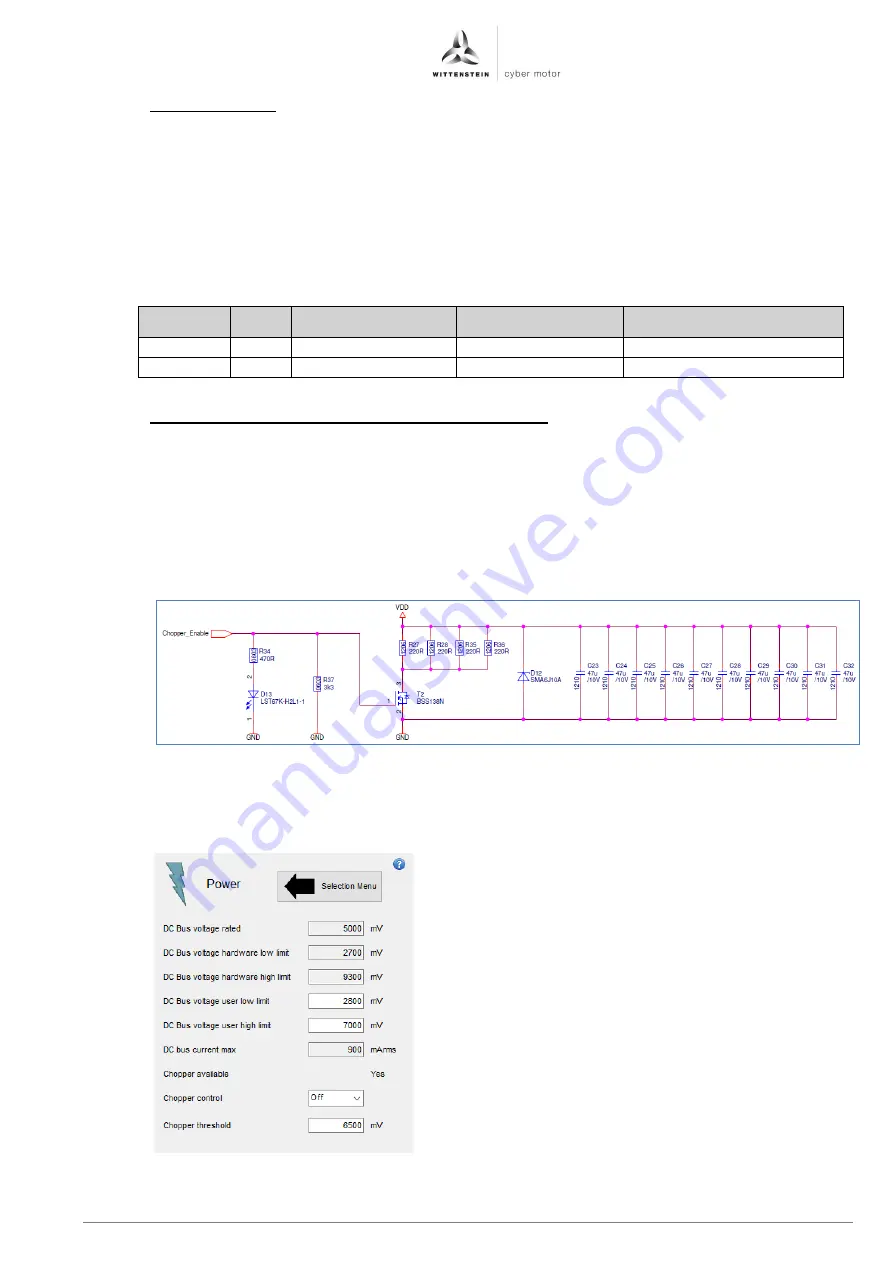
For this reason, the circuit on the starter kit is designed and implemented as illustrated in
figure 1.11.
Figure 1.11: Illustration of the circuit diagram section for implementing a brake chopper for dissipation of recuperation energy
This circuit module interacts with pin 1, Chopper_Ena, of the reaction wheel according to
table 5 and can be configured in the cyber
®
reaction wheel assistant in the power screen,
see figure 1.13.
Figure 1.12: Configuration of the pin for
dissipation of recuperation energy during
braking


