Project planning guide
cyber
®
reaction wheel 2
en-34
Doc. no.: 5022-D060586
Revision: 02
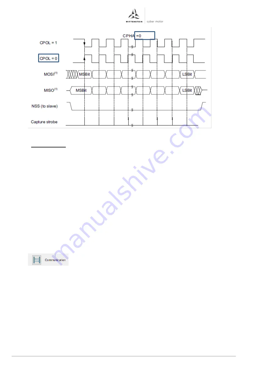
Figure 1.22: Illustration of SPI settings for CPHA and CPOL in the reaction wheel
3.4.3.3 UART interface
The UART bus is not a master/slave bus system but consists of equal stations.
The UART interface consists of two lines. The transmission line (Tx) of the controlling
microcontroller is connected to UART_RX and UART_TX at customer interface B, table 11, of the
starter kit or the interface to reaction wheel D, table 13.
Remember to set the "UART switching" selection switch, see figure 1.8, to UART uC.
As UART is a point-to-point connection, a separate UART channel must be provided for each
cyber
®
reaction wheel 2. Alternatively, a multiplexer switched by the microcontroller can be used.
UART settings:
Baud rate in Bits/s: adjustable: 9600, 19200, 38400, 57600, 115200 (default)
Data size:
8 bits
Parity:
no
Stop bits:
1
The default baud rate of 115200 bits/s is set on delivery and after a firmware update. Parameter
0x3E07 Communication UART Baud Rate can be used to change the baud rate. For a detailed
description of the baud rate setting, refer to parameter 0x3E07 in the CHM help.
The cyber
®
reaction wheel assistant offers a good starting point in the menu item
.


