cyber
®
reaction wheel 2
Project planning guide
Revision: 02
Doc. no.: 5022-D060586
en-37
4 Integration of the cyber
®
reaction wheel 2 into a satellite
4.1 Electrical integration of the cyber
®
reaction wheel 2
There are identical plug connectors on two sides of the reaction wheel. All three axes of rotation
of a Cartesian coordinate system can be mapped on the carrier board with only two different
mating connector arrangements (turned by 90°).
For positions of the connectors and the mounting threads, see dimensional
drawing 5007-D060499. Connector type and pin assignment are described in section 2.1.5.1.
The pin characteristic is explained in the following section 2.1.5.2.
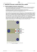
The connecting lines to the plug connector (routing, vias, etc.) that accommodates the reaction
wheel may only be implemented as closely as possible with the reaction wheel within a radius of
approx. 2 mm in compliance with the constraints illustrated in figure 1.23. The red border in figure
1.23 is the connector on the reaction wheel. With its housing, it protrudes beyond the connector on
the carrier board. For this reason, observe the information in the connector data sheet.
The manufacturer designation is MOLEX SlimStack PCB connector (16+2) 505066-1622.
There may not be any line on the outside of the carrier board in the remaining area below the
reaction wheel (see figure 1.23, shaded area) as the solder resist does not serve as reliable
insulation. A short circuit could occur at the housing or vias on the reaction wheel.
Figure 1.23: Illustration of constraints for integration of the cyber
®
reaction
wheel 2 on a carrier board


