


5
Additional camera registration
In the <
Install Wizard
> setting, make a connection to the camera automatically registered and use the menu
path to register and connect a camera.
Menu
;
Device
;
Camera
;
Cam Registration
;
Auto
a
b
c
e
d
To register a camera, follow these steps:
a
Select the camera to register (you can select multiple cameras).
b
Click the <
ID
> and <
P/W
> window to enter <
ID
> and <
P/W
> of the selected network camera. (If you do
not register a new ID/PW, then the default ID/PW combination is used.)
c
Click <
Connection Test
>.
d
Check the connection results.
e
If the channel connected successfully, click <
Register
> to end the camera registration process.
M
`
Click an item on the table to see a preview (you must change the ID and Password in step “
b
” if the camera account
changes).
`
Click the table headers to sort the content.
`
Click <
> to check if a new IP address was allocated to the camera when you rescan the network or when an IP
address was not assigned by the DHCP server (e.g., 192.168.1.100). If the IP still stays the same, then select Assign IP to
assign the IP manually.
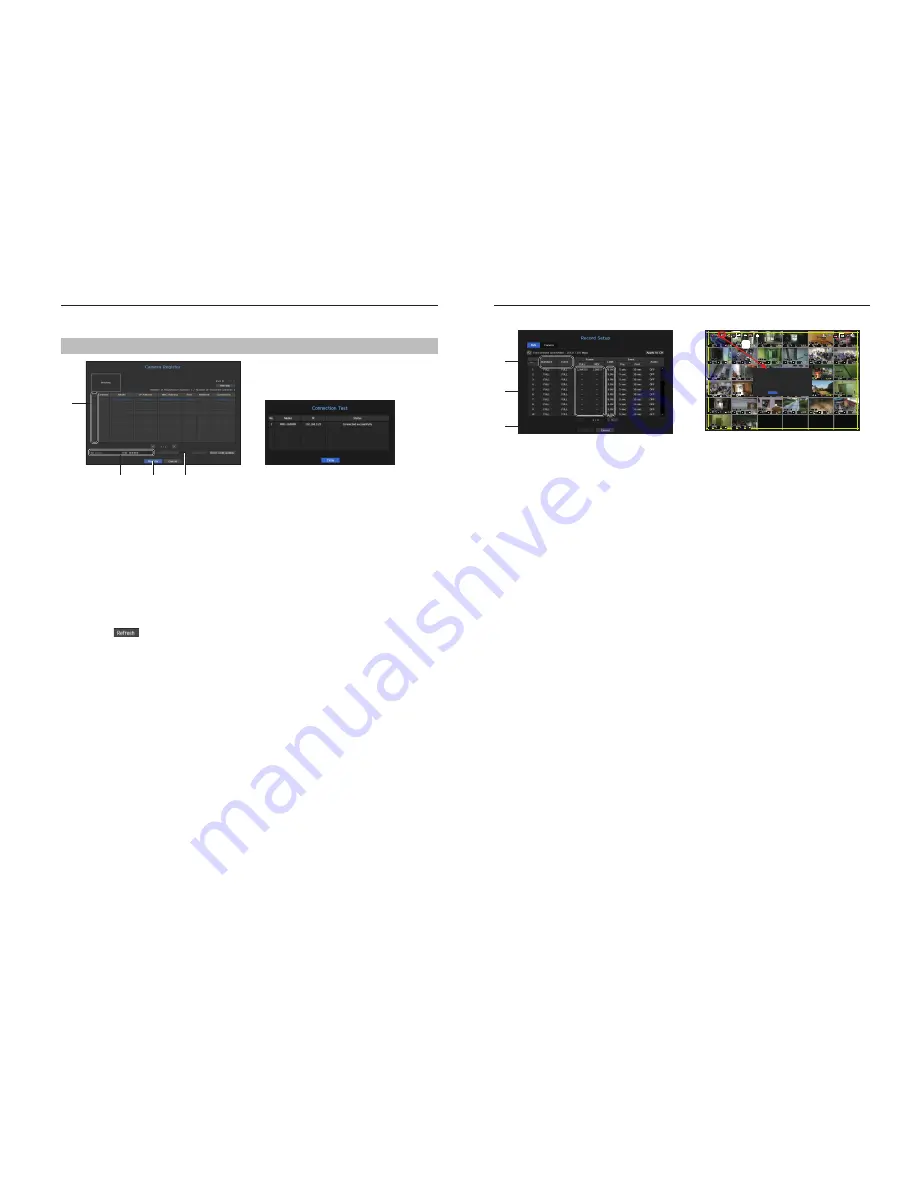
Configuring the Recording
This section outlines how to configure and view the recording settings for each channel.
a
b
c
FULL
NO
SCSI
Recording Restriction
Record data size exceeded limitation
Only key frames are recorded
Please check the record settings
Do not show this message again
OK
Record Status
d
a
Shows the standard and event recording method for each channel.
• FULL : Records all the frames received from the camera.
• KEY : Records only the key frames received from the camera. In general, one or two frames per second
are recorded, but you can adjust this in the camera settings.
• OFF : Turns off recording.
b
Shows the transmission size of the recording data for each channel.
c
Shows the data size limit for each channel.
M
`
The orange colored channel indicates the case where the
b
input data load is greater than the
c
permitted data load.
If you set the
c
permitted data load to greater than the
b
input data loads, it will be changed to orange.
`
If the sum of input data for each channel is greater than the max level for the camera, then
d
the recording exceeding icon
and the alarm message will be displayed. In this case, for the channel exceeding the input limit will record the main
frame(one or two per second) only.


