MI 1069 18
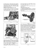
adjustments. When mounting spark plug,
tighten
28
to
30 ft. lbs
of torque..
VALVES and SEAT INSERT (Fig’s. 22, 23, 24)
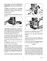
Take off valve inspection cover and gasket. By means
of a standard automotive valve lifter, remove retainer
locks and take out valves from top of cylinder block.
Caution: Do not damage breather reed in spring
compartment, when inserting lifter tool.
Clean out carbon and gum deposits from the valves,
seats, ports and guides. Replace valves that are badly
burned, pitted or warped.
The
exhaust valve face
and replaceable exhaust
seat
insert
are of
stellite
material. The inlet seat is an
integral part of the cylinder block. A
positive
type
valve rotator
is furnished on the exhaust valve. A
faulty rotator may be the cause of a burned exhaust
valve face or seat, and thus should be replaced.
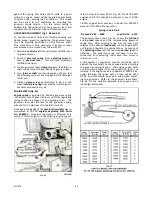
The exhaust valve
seat insert
can be removed when
replacement becomes necessary, by means of
Wisconsin Motor
DF-66-A
insert puller.
See Fig. 23.
Grinding of valves
and
seats
should be done by an
authorized Wisconsin service station. See directory in
rear of manual.
Before grinding, inspect valve guides for possible
replacement. Refer to
Fig. 25
for proper method of
driving out guides, and see chart,
Fig 24
for valve,
seat and guide specifications.
After grinding, lap valves in place until a uniform ring
will show entirely around the face of the valve. Wash
valves and block thoroughly with gasoline or kerosene
and
do not assemble valve springs
until tappet clear-
ance has been checked.
See ‘Tappet Adjustment’.
VALVE GUIDES
When valve stem clearance becomes excessive, the
valve guides should be driven out, as illustrated in
Fig. 25,
and new guides pressed in place. Use
Wisconsin Motor
DF-72
valve guide driver. In reassem-
bly, press guides into valve ports with the
internal
chamfer in guide pointing downward
. Refer to
Fig. 24
for clearance specifications and proper assembly.
Summary of Contents for Air Cooled TR-10D
Page 6: ...MI 937 2 4 Fig 1 289860C TAKE OFF rear and LEFT HAND SIDE VIEW of ENGINE...
Page 7: ...5 MI 938 2 FAN END front and RIGHT HAND SIDE VIEW of ENGINE...
Page 8: ...MI 939 2 6 SECTIONAL VIEWS OF ENGINE...
Page 28: ......
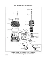
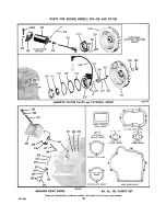
Page 29: ...PARTS FOR ENGINE MODELS TRA 10D AND TR 10D...
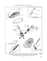
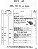
Page 30: ...PARTS FOR ENGINE MODELS TRA 10D AND TR 10D...
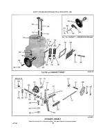
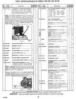
Page 31: ...PARTS FOR ENGINE MODELS TRA 10D AND TR 10D...
Page 32: ......
Page 33: ......
Page 34: ......
Page 35: ......
Page 36: ......
Page 37: ......
Page 38: ......
Page 39: ......
Page 40: ......
Page 44: ......
Page 46: ...WISCONSIN MOTOR CORPORATION MILWAUKEE WISCONSIN 532466 PRINTED IN U S A...


