11 MI-1062
a weak spark or no spark at all, follow instructions in
“
Breaker Point Adjustment”
paragraphs. Also check
ignition wires, spark plugs, condenser and coil.
MAGNETO IGNITION
MAGNETO
The flywheel magneto used on this model of engine is
a product of either the
Fairbanks-Morse
or
Wico
Electric
companies. The magneto is made up of three
component parts;
flywheel, stator plate
with coil, and
breaker assembly.
The
breaker box
is an integral part of the crankcase,
and the
points
and
condenser
contained there-in are
used for either Wico or Fairbanks-Morse magnetos.
The other components;
flywheel
and
stator plate
, must
be of the same manufacturer when service replacement
becomes necessary. In other words
do not
use a Wico
flywheel with a Fairbanks-Norse stator plate or vice
versa. The manufacturers name is cast on these parts
for identification.
If
oil
, leaks from breaker box, refer to
“Crankcase
Breather”
cleaning for cleaning of breather valve seat.
BATTERY IGNITION
IGNTION COIL – 12 Volt
Engines furnished with battery ignition, instead of the
standard magneto ignition system, uses a conventional
12 volt ignition coil. The same
breaker point assem-
bly
is used for both types of ignition, but the
flywheel
and fan end
bearing plate
differ.
The following
“Breaker Point Adjustment”
and
“Tim-
ing”
procedures apply to both
magneto
and
battery
ignition
systems.
BREAKER POINT ADJUSTMENT
The
breaker points
are contained in the
breaker box
on the left hand side of the engine. The points are
actuated by a
push pin
operating off the camshaft.
The hardened
steel head of the push pin contacts the
breaker cam
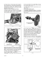
on the camshaft, as illustrated in
Fig. 10.
At least twice each season or when ignition spark
becomes weak, remove breaker box cover, inspect the
points and check the gap opening. If there is evidence
of pitting or pyramiding and it becomes necessary to
resurface or replace point, it will also be necessary
to readjust the gap to its proper clearance, and re-
time the engine.
The normal breaker point gap is
0.020 inch
at full
separation. However; the fixed
running spark advance
of
18°
is regulated by the point opening, and thus a
slight variation in gap opening may occur when ob-
taining an accurate spark advance.
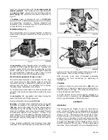
With reference to
Fig’s. 10 and 11
, adjust breaker
point gap as follows, and then proceed as per instruct-
tions in
Timing
paragraphs.
1. Turn engine over by means of the starter sheave
until
breaker arm push pin
is at the highest point of
the cam (maximum point opening).
2. Loosen
contact support plate lockscrew
just enough
so that plate can be moved.
3. Place a
0.020 inch
feeler gauge between points.
4 Insert a screw driver into
adjusting slot
(earlier
model engines had an adjustment cam) and open or
close the contacts, by moving the plate, until
proper point gap is obtained.
5. Tighten
lockscrew
and recheck breaker point gap.
TIMING
MAGNETO or BATTERY IGNITION
The fixed
running spark advance
of
18
°
is regulated by
the breaker point opening and reasonably accurate
timing is obtained by simply setting the breaker point
gap to
0.020 inch
, as explained in
“Breaker Point
Adjustment”
. However,
static timing
with a
continuity
light,
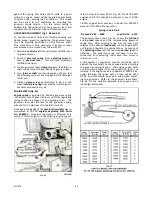
as illustrated in
Fig. 12
, is more accurate and
advisable. The timing light is Wisconsin Motor part
number
DF-81-S1
.
The accuracy of the timing can be checked with a
neon lamp
and the engine running at operating speed.
It is however, not advisable to adjust the timing while
engine is running. See
“Static Timing Procedure”
.
A
timing pointer
is located on the right hand side of
the flywheel shroud, to indicate the correct place-
ment of the flywheel
advance timing mark
.
STATIC TIMING PROCEDURE:
See Fig. 12.
1. Disconnect
coil primary wire
at bottom of breaker
box. Remove breaker box cover.
2. Grooved
timing mark
on
flywheel
can be observed
thru the opening on right hand side of flywheel
shroud.
Summary of Contents for Air Cooled TR-10D
Page 6: ...MI 937 2 4 Fig 1 289860C TAKE OFF rear and LEFT HAND SIDE VIEW of ENGINE...
Page 7: ...5 MI 938 2 FAN END front and RIGHT HAND SIDE VIEW of ENGINE...
Page 8: ...MI 939 2 6 SECTIONAL VIEWS OF ENGINE...
Page 28: ......
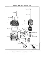
Page 29: ...PARTS FOR ENGINE MODELS TRA 10D AND TR 10D...
Page 30: ...PARTS FOR ENGINE MODELS TRA 10D AND TR 10D...
Page 31: ...PARTS FOR ENGINE MODELS TRA 10D AND TR 10D...
Page 32: ......
Page 33: ......
Page 34: ......
Page 35: ......
Page 36: ......
Page 37: ......
Page 38: ......
Page 39: ......
Page 40: ......
Page 44: ......
Page 46: ...WISCONSIN MOTOR CORPORATION MILWAUKEE WISCONSIN 532466 PRINTED IN U S A...


