MI-1075 24
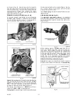
against the spring and closes the throttle to a point
where the engine speed will be maintained practically
constant under varying load conditions. This speed
can be varied to suit conditions by adjusting the
governor spring tension. An idle return spring is
hooked into the upper end of the governor lever and
connected to the breather tube on the tappet cover.
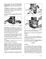
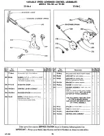
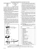
GOVERNOR ADJUSTMENT (Fig’s. 44 and 45)
To maintain correct carburetor throttle opening and
obtain proper governor regulation, the governor lever
must be properly positioned on the fulcrum shaft.
This procedure is only necessary if governor lever
was loosened or removed from fulcrum shaft.
1. Assemble
control rod,
from carburetor throttle lever
to governor lever.
2. Connect
governor spring,
from
adjusting screw
to
hole in
governor lever
. This will hold carburetor
throttle wide open.
3. Loosen governor lever
clamp screw
so that fulcrum
shaft can be turned independently of governor lever.
4. Turn
fulcrum shaft
counter-clockwise until you feel
the internal governor vane stop against the flyweight
thrust pin.
5. Tighten
clamp screw
as illustrated in
Fig. 44
, and
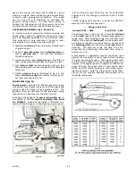
mount
idle return spring
from breather tube to gover-
nor lever as shown in
Fig. 45
.
ENGINE SPEED (Fig. 45)
Engine speed
is adjusted by hooking governor spring
into correct hole of governor lever, and then regulating
spring tension by means of an adjusting screw. The
governor lever has
8
holes for the governor spring,
with the No. 1 hole closest to the fulcrum shaft.
A change in the design of the
governor flyweights
was in-
corporated in TR-10D
engines beginning with Serial
No. 3909152.
Governor regulation is affected as a
result of this change, so in readjusting engine speed,
refer to
Governor Lever Chart, Fig. 45
, for all TRA-10D
engines and if this change is pertinent to your TR-10D
engine.
TR-10D engines built previous to Serial No. 3909152
were set for full throttle operation:
Spring in Hole No. 2
No Load R.P.M. – 3800 Load R.P.M. – 3450
The governor lever chart,
Fig. 45,
shows the
full load
and
no load
speeds and the corresponding governor
spring hole. After hooking spring into the lever hole
relative to the desired
load speed
, run the engine with-
out load and regulate the spring tension by means of
the
adjusting screw
until the required
no load
speed is
obtained. The governor spring will have to be dis-
connected from adjusting screw each time screw is
turned in or out.
A tachometer or revolution counter should be used
against the crankshaft to check speed while adjusting
the governor spring tension. The engine speed with-
out load will be higher than the speed with load. For
instance, if the engine speed is to operate at 3000 R.P.M.
under full load, the speed with no load will be 3230
R.P.M. and this should be kept in mind when adjust-
ing the governor. Refer to the governor lever chart,
Fig. 45,
for the variation between load speed and no
load (high idle) speed.
Summary of Contents for Air Cooled TR-10D
Page 6: ...MI 937 2 4 Fig 1 289860C TAKE OFF rear and LEFT HAND SIDE VIEW of ENGINE...
Page 7: ...5 MI 938 2 FAN END front and RIGHT HAND SIDE VIEW of ENGINE...
Page 8: ...MI 939 2 6 SECTIONAL VIEWS OF ENGINE...
Page 28: ......
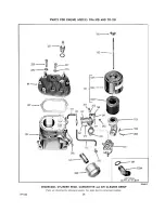
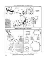
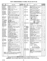
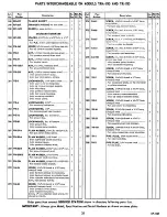
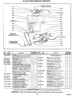
Page 29: ...PARTS FOR ENGINE MODELS TRA 10D AND TR 10D...
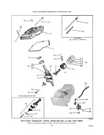
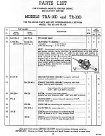
Page 30: ...PARTS FOR ENGINE MODELS TRA 10D AND TR 10D...
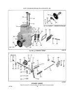
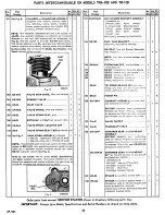
Page 31: ...PARTS FOR ENGINE MODELS TRA 10D AND TR 10D...
Page 32: ......
Page 33: ......
Page 34: ......
Page 35: ......
Page 36: ......
Page 37: ......
Page 38: ......
Page 39: ......
Page 40: ......
Page 44: ......
Page 46: ...WISCONSIN MOTOR CORPORATION MILWAUKEE WISCONSIN 532466 PRINTED IN U S A...


