background image

WiNRADiO G305 User’s Manual


63 

Therefore, while increasing the filter lengths, always watch the CPU usage 
(shown at bottom left of the demodulator 

Setup

 window) in order not to starve 

the operating system of CPU resources (80% is a good upper limit). Starving  
the system of CPU resources manifests itself by the computer becoming 
sluggish or possibly "freezing" entirely. 


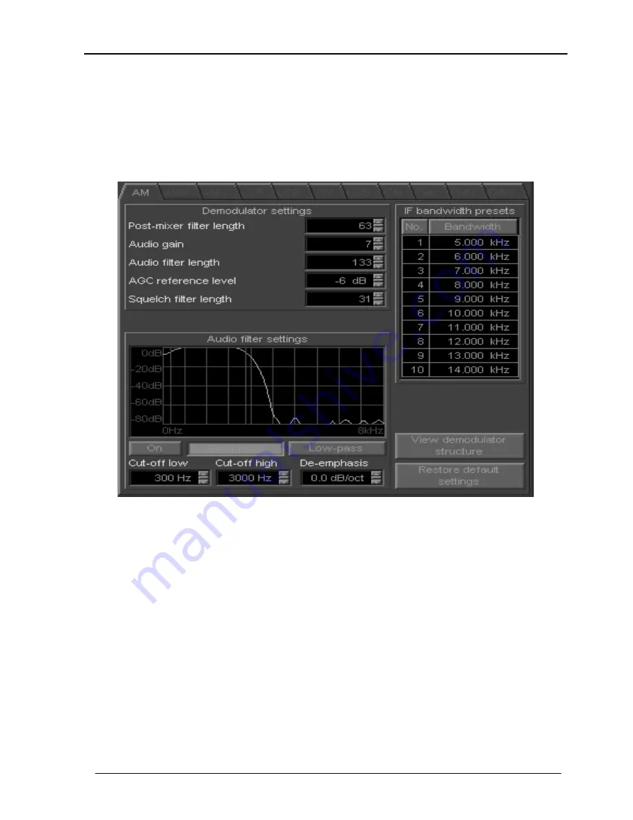
The first parameter, 

Post-mixer filter length

 parameter refers to the post-

mixer low-pass filter, whose cut-off frequency is automatically related to the 
currently selected 

IF bandwidth

. For AM, AMN, AMS, CW, DSB, ISB, FM6 

and FMN modes, the post-mixer filters bandwidth is half of the IF bandwidth, 
while for LSB and USB both bandwidths are equal to the IF bandwidth. The 
factory default length is 63. Reducing this value will decrease the receiver 
selectivity and make the receiver more prone to interference from nearby 
strong signals. However, for slower computers it may be necessary to 
compromise on this figure if the demodulator appears too slow (to the point of 
the panel "freezing" or drop-outs of audio) because of insufficient CPU 
resources. If your CPU speed allows it, then we would recommend to set this 
value to its maximum limit (511). 

Summary of Contents for G305

Page 1: ...WiNRADiO G305 VHF UHF Receiver User s Guide ...

Page 2: ...may be reproduced or transmitted in any form or by any means without the written permission of the publisher Trademarks WiNRADiO G3 and G305 are trademarks of WiNRADiO Communications All other brand and product names are trademarks of their respective owners Patents WiNRADiO technology is protected by US Pat No 6 289 207 and other pending US and international patent applications Printed in Austral...

Page 3: ... adapters must be used Operation with non certified cables power adapters and peripherals may result in interference to radio and TV reception Modifications Any changes or modifications to the WiNRADiO receiver could void the user s authority to operate this equipment as well as void the manufacturer s warranty Limitation of Liability and Remedies The information published in this book has been co...

Page 4: ...st Tuning Pad 24 Setting the Modulation Mode 24 Volume Control 26 Mute Control 26 Audio Filter 26 AGC 27 IF Gain 28 Software AGC 28 AFC 29 RF Gain 29 Squelch Control 30 Frequency Stepping 32 Frequency Memory 33 Scanning 40 S meter 45 Power Switch 46 Date and Time Displays 46 Spectrum Scope 47 Appendix A Troubleshooting 50 Appendix B Sound Card Controls 55 Appendix C Dealing with Interference 57 Ap...

Page 5: ...orward and make it available at an affordable price In designing the WiNRADiO G305 receiver we strived to provide the optimum balance of sensitivity selectivity and dynamic range yet maintaining low cost and implementing a number of significant features previously available only on receivers significantly more expensive bulky and far less friendly to the user While we have implemented many more fe...

Page 6: ...ctors the antenna connector SMA type 50 ohm and 12 kHz IF intermediate frequency output The signal from the 12 kHz IF output is normally connected to the PC sound card where it is digitized to be then processed by the PC The advantage of this model is that it does not require any external power supply and does not occupy any additional desk space The receiver is very well shielded to prevent any i...

Page 7: ...ombines the 12 kHz IF intermediate frequency output USB interface and serial interface Normally only the USB interface cable is supplied and the IF signal arrives from the receiver to the PC already digitized via the USB cable This method is preferable because it relies on a high quality analog to digital converter inside the receiver and guarantees optimum and consistent performance The installat...

Page 8: ...zation of the 12 kHz IF signal it requires careful adjustment of the input signal level The performance will depend on the sound card quality similarly to the internal G305i model It is a suitable method in situations where the receiver needs to be controlled by computer systems without the USB interface Did you know DRM Digital Radio Mondiale is a new digital broadcasting system for medium and sh...

Page 9: ...n your IBM PC compatible computer must meet the minimum system requirements specified below System Requirements Minimum Recommended CPU 500 MHz Pentium III 1GHz or higher Pentium IV or Athlon RAM 64 MB 256 MB or more Display SVGA SVGA 16 mil colors HD free space 20 MB 40 MB Sound card SoundBlaster compatible 16 bit full duplex Creative Sound Blaster 16 or 32 bit OS Windows 98 ME 2000 XP Windows XP...

Page 10: ...sh down until it is firmly seated Screw the metal bracket at the end of the card to the computer case This must be done to provide proper grounding for the card 4 Replace the computer case and reconnect the power cord 5 Connect the supplied audio lead between the receiver output a standard audio jack and the sound card Line Input If there is no Line input on your PC as is the case with some laptop...

Page 11: ... using the power switch at front of the receiver The blue LED will blink to indicate that the receiver is powered up G305e receiver with USB interface Did you know USB Universal Serial Bus is a modern interface standard designed to replace the slow RS 232 serial standard USB version 1 0 makes it possible to transfer data at 12 megabits per second The newer USB version 2 0 is 40 times faster The G3...

Page 12: ...t If there is no Line input on your PC as is the case with some laptops you may use alternative inputs such as the Microphone input This may be also necessary with certain types of sound cards such as Creative Audigy 2 3 Plug the supplied power adapter to the power outlet and connect its output to the receiver 4 Turn the receiver on using the power switch at front of the receiver The blue LED will...

Page 13: ...radio on ready 5 Two short flashes USB connection radio off 6 One short flash followed by a long one USB connection radio on ready 7 Two short flashes followed by a long one USB connected but driver not installed 8 Three short flashes USB connected driver installed but application not running yet For the normal Ready states as indicated by patterns 6 for USB or 4 if the optional RS 232 serial inte...

Page 14: ...e is simple Place the antenna as close to the window as you can and keep the active part of the antenna as far away from the PC and other electrical devices and metal objects as possible No matter how good a radio receiver is the performance of the entire receiving system will depend on the quality of the antenna The same applies to a WiNRADiO receiver To make the most of your WiNRADiO receiver yo...

Page 15: ...n the installation program which will also install the drivers Setting up the Sound Card This section refers to the G305i model or the G305e model with serial interface only The G305e model with the standard USB interface does not require this set up and this entire section may be skipped After installing the hardware and software you will need to set up the sound card parameters This is done both...

Page 16: ...ol Panel setting specified under Start Settings Control Panel Multimedia Properties Audio If a sound card is specified in this Control Panel setting for both playback and recording this is very likely but not always necessarily so then you can simply select Windows Default as the wave device for the demodulator Otherwise the specific name of the sound card should be selected ...

Page 17: ...ere the left and right inputs are swapped Normally the G305 Demodulator expects the receiver output to be connected to the right sound card input If it is to be connected to the left input instead the reverse input line needs to be selected from the drop down list With some laptops only the Microphone input may be available and you will need to connect the receiver to the Microphone input instead ...

Page 18: ...usually this will be Line or Microphone input This may seem a bit unexpected Why are we muting the input line This is because the signal coming from the receiver is not an audio signal but rather the intermediate frequency signal It needs to be processed demodulated by the PC first before it is output back to the sound card That s also why the sound card needs to be full duplex to allow for such s...

Page 19: ...eceiver can be attributed to an incorrect sound card setting Typical problems include Not selecting the Mixer device or Mixer line correctly which will manifest itself by the absence of any signal appearing in the spectrum scope Failing to adjust the Input level properly which may result either in low or no audio output or on the other hand distortion if the signal level is too high Note Some soun...

Page 20: ... WiNRADiO G305 Receiver We hope you will return to that chapter as the WiNRADiO G305 receiver has many fine features which it would be a shame to miss Start the WiNRADiO G305 receiver application double clicking on the WiNRADiO icon The WiNRADiO G305 receiver control panel will appear as shown below WiNRADiO G305 Receiver Control Panel The WiNRADiO G305 receiver control panel has some elements sim...

Page 21: ...i clockwise respectively If you place your cursor in the bottom half of the tuning knob the direction of the rotation will reverse The rotation increment of the tuning knob is 0 5 kHz This can be changed easily using the Shift Ctrl or Alt keys If you press the Shift key while tuning the increment will increase ten times to 5 kHz Pressing Ctrl will increase the increment a hundred times 50 kHz On t...

Page 22: ...iNRADiO G305 Receiver Frequency Display The up and down buttons under the individual digits make it possible to quickly step up or down the frequency in the corresponding positions The little slider buttons between the buttons can be used for faster adjustment Under these buttons there is a band description window This shows the band allocation of the currently tuned frequency These band descripti...

Page 23: ...onvenient feature if you wish to tune quickly across a frequency range hold the mouse button and accelerate the movement by pressing the Shift or Ctrl keys On the other hand pressing the Alt key will reduce the tuning step ten times A similar function is performed by the Tune Step Multiplier buttons Normally the x1 button is down by default When x0 1 or x10 are pressed the rotation of the tuning w...

Page 24: ...cy and step through the band with the appropriate step size Setting the Modulation Mode To select the modulation mode click on the appropriate Mode button in the Demodulator panel WiNRADiO G305 Standard Demodulator Panel The real time spectrum display shows the output of the receiver i e the intermediate frequency signal as it is applied to the PC sound card When you press the mode buttons you wil...

Page 25: ...cy and to select the correct AM mode to avoid interference from adjacent signals The optional FMW wide FM broadcast FM mode is a special case amongst the modulation modes Please refer to Appendix F Wide band FM Option If this option is not installed the FMW button is disabled If you also purchased the optional Professional Demodulator you can select this demodulator from the Demodulators top bar m...

Page 26: ...on to drag the slider up or down and the volume will change accordingly Finally another convenient way of changing the volume is by using the Left and Right Cursor keys on the keyboard Mute Control Next to the Volume control is the Mute button which allows you to switch off the audio output quickly It is faster to use than setting the volume to zero with the added benefit of not changing the set v...

Page 27: ...he transmission The demodulated signal will then sound better with a slow AGC as the receiver will not have time to increase the gain during the off intervals and increase the background noise causing a raspy sound On the other hand use fast AGC when listening to especially weak signals buried in static and noise Otherwise each new burst of noise would desensitize the receiver for a long time and ...

Page 28: ... when the AGC is switched off The gain value ranges from 0 to 100 where 100 corresponds to maximum gain The gain can be adjusted in three ways by typing the value directly in the edit box by using the up and down arrow buttons or by dragging up or down the center slider Software AGC The Software AGC facility is available in the demodulator panel and provides a supplementary function to the main AG...

Page 29: ...d be off and the Preamplifier should be on for maximum receiver sensitivity Turning the Attenuator on reduces the receiver sensitivity by 18 dB i e 6 times while switching the Preamplifier off results in a further reduction by approx 12 dB Attenuator and Preamplifier Why would you ever need to reduce the sensitivity Because unusually strong signals from local stations may occasionally cause overlo...

Page 30: ...ferent types of squelch to maximize operator convenience and to make scanning more efficient and faster Level squelch refers to the received signal strength as it is indicated by the S meter If the signal strength is higher than the specified threshold the squelch will open and the receiver will be unmuted Noise squelch determines the level of noise in the received demodulated audio below which th...

Page 31: ... this also disables the S meter but all other squelch types still remain active and can be used with the manual IF gain setting To adjust the Level squelch control first tune to an unoccupied frequency that produces only noise Increase the squelch until the receiver is muted You will see the red colored segment of the S meter growing until it gets higher than the current S meter value At that mome...

Page 32: ...ttons on the right of the display to select from commonly used step sizes For convenience you can also use the small slider between the two buttons Frequency Stepping Panel When the step size is selected you can step up or down from the currently displayed frequency using the left right arrow buttons under the Step size display The double arrow buttons further down will cause stepping by a step si...

Page 33: ...ed to associate particular mode and squelch settings with specified frequency ranges To configure the auto stepping ranges go to Options Autostepping in the top bar menu The following window opens You can use the New button to add a new range For each range you need to specify the Lower and Upper ends of the range Step size and optionally Mode Squelch and Description You can specify as many such b...

Page 34: ... can store several attributes mode callsign user comment group assignment squelch and a hotkey To store a frequency into memory the receiver must first be tuned to that frequency and the appropriate mode must be selected if you also wish to store the mode Next click on the S button in the Memory Control Panel as shown above A Store frequency dialog box will pop up allowing you to assign a memory n...

Page 35: ...if you wish including one which is already allocated The third item contains the group assignment buttons You can assign the frequency to one or more of 16 different groups whose meaning you define yourself When you are searching or scanning for a particular type of frequencies for example Airforce the group assignment will allow you to confine the searching and scanning to that particular type No...

Page 36: ...uelch values can also be stored which will then be set automatically when the frequency is recalled Finally a Memory Scan Lock out can be set for each memory which means that the memory will not be included in a memory scan In the memory Recall window such memories will be shown with a small x preceding the memory number Finally when everything has been set click on OK or press Enter to save the n...

Page 37: ...ency open the Recall frequency dialog box as described in the previous section Select the item you want to edit and click on Edit alternatively double click on the item A dialog box will pop up showing the current settings All the settings including the memory number can be edited After the entry has been edited click on OK Deleting a Frequency To remove a frequency open the Recall frequency dialo...

Page 38: ...og box will pop up allowing you to choose a memory file to load Memory Stepping Memory stepping makes it possible to step through frequencies stored in the current memory file To step through memory frequencies use the left or right arrow buttons located under the memory S and R buttons The double arrow buttons located further down make it possible to advance ten frequencies up or down or to the s...

Page 39: ...h value Secondary squelch type Secondary squelch value Mode Callsign Comments We recommend exporting an existing memory file and examining the format of the exported CSV file before attempting to import third party data Did you know Each memory file you create can contain up to 10 000 frequencies You can have as many memory files as you wish Each frequency consumes approximately 100 bytes of hard ...

Page 40: ...press the Pause button marked with two vertical bars A signal is considered found when it satisfies the squelch conditions For example if Level squelch is selected then the signal level must be higher than the specified threshold for the squelch to open Correct setting of the squelch threshold is therefore essential for scanning If you set the squelch level too low the scanning will stop even if t...

Page 41: ...eed to further specify the conditions under which the scanning will Resume The conditions to resume can be one of the following 1 When the signal disappears i e the scanning resumes immediately when the signal disappears 2 After a certain user defined Delay time i e no matter if the signal disappears during this Delay Time or not the software will always wait for the Delay Time interval then resum...

Page 42: ...oups only Exclusions Sometimes it is desirable to exclude certain frequencies from scanning This means that such specified frequencies should be ignored even if the signal level on these frequencies is higher than the squelch The WiNRADiO G305 receiver application makes it possible for multiple frequency ranges to be excluded This is done using the Exclusions button When you press this button you ...

Page 43: ...ote the check box at the start of every specified range This allows you to selectively enable and disable ranges to be scanned without having to delete and re enter them To define a new range use the New button This will open a dialog box where you will be asked to specify lower and upper limit frequencies of the range the modulation mode squelch settings and optionally a description You can enter...

Page 44: ...Scan Backward buttons will resume the action from the paused frequency If you stop scanning with the Stop button then using the Scan Forward or Scan Backward buttons will recommence scanning from the initial or the last frequency again If no ranges are specified in the Ranges list then activating scanning in the Range mode will result in no action An additional useful feature of frequency range sc...

Page 45: ... the top bar menu Groups can be enabled disabled using the check box Enable group restriction in the same window S meter The WiNRADiO G305 receiver Signal Strength Meter S meter makes it possible to measure signal strength in either S units dBm or µV microvolts The units are selected by correspondingly marked buttons on the right side of the display In the microvolt mode the p p button is also ena...

Page 46: ... powered down and no sound will be heard through the speaker or headphones When you exit and restart the receiver application the power status at exit will be remembered Date and Time Displays The clock display located under the Fast Tuning Pad indicates the current time and date The UTC clock shows Universal Coordinated Time formerly called GMT Greenwich Mean Time which is the standard time used ...

Page 47: ... the swept spectrum is approximately 1 kHz If you select step sizes larger than this value you may be missing some parts of the spectra This is actually not always such a bad thing If you know the channel separation on the band it is advantageous to set the step size equal to this channel separation for example on VHF UHF bands it is often 12 5 or 25 kHz Stepping with larger step size speeds up th...

Page 48: ...eceiver If you press the Hits button the spectrum display changes to a Hit Counter The Hit Counter makes it possible to plot a histogram of hits for frequency channels within the specified frequency range A hit is an instance when the signal satisfies the squelch conditions for the given frequency This makes it possible to observe and monitor traffic on particular channels over a period of time an...

Page 49: ...step size is made equal to the channel spacing on the band For example on many VHF UHF bands the spacing is 12 5 or 25 kHz Making the step size the same as the channel spacing and the start frequency equal to that of the first channel in the band will ensure that each step will fall on the center of a channel This will maximize the spectrum sweeping speed and ensure the best graphical representati...

Page 50: ...is located in the sound card control panel note the button Advanced under the microphone volume control Sometimes this checkbox or button is marked 20 dB booster See also the problem below for another possible cause of this problem Problem I can hear the audio and tune the receiver but the sound is distorted Solution Check if the AGC is switched on i e either the Slow Med or Fast buttons are down ...

Page 51: ...from the speaker Solution Check if you see any noise appearing in the demodulator spectrum scope under the AM AMS etc mode selection buttons If there is a flat line or only very little noise visible check the following The receiver output is connected to the sound card Line input using the supplied cable If your PC sound card does not have a Line input you can use alternative inputs such as Microp...

Page 52: ... input are properly selected this panel is accessible under the Setup button in the demodulator panel The sound card has the left and right inputs reversed Normally the G305 Demodulator expects the receiver to be connected to the Right input Using the reverse input makes the demodulator use the Left input instead This is a very rare problem so use this only when all other possible remedies have be...

Page 53: ...utton in the demodulator panel is released too and the speaker output of the sound card is unmuted in the sound card control panel Problem G305i or G305e with serial interface option only I can hear the audio but it is not a pleasant sound There is an interfering high pitch tone Solution You need to mute the Line input in the sound card control panel see the panel on the next page What you are pro...

Page 54: ...n the antenna is picking up too much ambient noise Try to improve the antenna or move it further away from the PC Additional noise defeating measures may be in order see also Appendix C Dealing With Interference Problem Reception is obscured with a buzzing interference Solution Check for the sources of interference in your surroundings it could be fluorescent lights a lamp dimmer or some other hou...

Page 55: ...he Playback section is then used to output the demodulated audio signal to the speaker s For the WiNRADiO G305 application there is a need to independently control both sound card sections The Recording section volume needs to be adjusted to provide the correct IF signal level for the demodulation process the Playback section control is needed to be able to control the speaker volume Typically you...

Page 56: ...w volume control on the taskbar Control Panel Sounds and Multimedia Audio tab Sound Playback à Volume button Sound Recording à Volume button XP Control Panel Sounds and Audio Devices Sounds tab Checkbox Place volume icon in the taskbar Control Panel Sounds and Audio Devices Audio tab Sound Playback à Volume button Sound Recording à Volume button Did you know The ubiquitous PC sound card was invent...

Page 57: ...ful signals and interference The interference from your PC can either radiate directly to the antenna or it can be conducted to it along the outer conductor of the lead in cable Even in professional radio receiving stations a lot of care and effort is always needed if this type of self interference is to be avoided Some computers are worse than others in terms of generated electromagnetic interfer...

Page 58: ...e Attenuator in the receiver control panel You may also try shortening the antenna If you live very close to a strong local transmitter these measures may be insufficient In such case you should be able to eliminate intermodulation by fitting a special filter to your antenna to reduce the level of the signals causing the interference The design and application of such filters falls beyond the scop...

Page 59: ...to promote and encourage such experimentation The WiNRADiO G305 receiver represents only one half of the entire radio The other half is your PC The receiver hardware contains the following functional blocks The incoming signal from the antenna in the 9 kHz to 1800 MHz range is filtered and amplified then fed into a mixer Here it is mixed with the first LO local oscillator which is performed by a D...

Page 60: ...is is in order not to cause desensitization of the receiver in the presence of neighboring strong signals falling within the 15 kHz IF bandwidth The resulting variation in audio output is then compensated for in software using Audio AGC in the software demodulator The final IF bandwidth is then adjusted entirely in software If the Professional Demodulator is used this bandwidth is continuously var...

Page 61: ...t of software defined shortwave receiver a step further The main differences between the Standard and the Professional demodulator are as follows Additional demodulation modes DSB and ISB Continuously variable IF bandwidth from 100 Hz to 15 kHz User adjustable IF filter coefficients and other parameters User adjustable software AGC User adjustable audio filter User definable IF bandwidth presets I...

Page 62: ...the real time spectrum scope the currently selected IF bandwidth is indicated using a different background color The portion of the real time signal spectrum falling within the IF bandwidth is shown in yellow Adjusting Demodulator Parameters Each demodulation mode has its own associated set up panel accessible under the Setup button located under the CW mode button By selecting the mode either usi...

Page 63: ...lly related to the currently selected IF bandwidth For AM AMN AMS CW DSB ISB FM6 and FMN modes the post mixer filters bandwidth is half of the IF bandwidth while for LSB and USB both bandwidths are equal to the IF bandwidth The factory default length is 63 Reducing this value will decrease the receiver selectivity and make the receiver more prone to interference from nearby strong signals However ...

Page 64: ...sables filtering and is tied to the AF Filter button in the demodulator front panel The Band pass and Low pass buttons make it possible to select the desired type of filter The filter cut off frequencies can be either entered numerically or the filter edges can be dragged with the mouse For the band pass filter the entire filter passband may be shifted left or right by dragging the top horizontal ...

Page 65: ...ation and study where the effects of various filter settings can be easily observed and optimized The entire demodulation process can be observed in the demodulator structure window accessible from within the demodulator settings press the Setup button under the CW mode button then the large View Demodulator Structure button Each mode has its own associated structure By selecting the mode either u...

Page 66: ...ge to blue If both displays are connected to the same test point the point color will turn magenta Within the displayed spectra a red color frequency cursor can be manually dragged using the left mouse button over a particular spectral component The two Vector Voltmeter displays labeled Left Right indicate the relative amplitude and phase difference between the two spectral components at the curso...

Page 67: ...mode the displayed structure of the demodulator will change accordingly allowing you to exploring it For example for the AMS mode synchronous AM demodulation the G305 Professional Demodulator uses a digital carrier recovery technique based on the so called Costas loop Synchronous AM Demodulator Structure Did you know Synchronous AM demodulation mode is particularly useful when listening to an ampl...

Page 68: ...t any intervening re digitization process and therefore without introducing any additional distortion to the received signal If the WiNRADIO Virtual Sound Card is not used leave these two checkboxes unchecked Did you know If you intend to use external third party decoding or signal processing programs the WiNRADiO Virtual Sound Card offers major advantages By eliminating sampling rate differences ...

Page 69: ...tained conventional hardware defined receiver within a receiver The user can receive wide FM broadcasts but cannot see the entire 230 kHz bandwidth in real time or adjust the IF bandwidth Instead the real time spectrum panel shows demodulated audio spectrum This option is available for both G305i and G305e receiver models The Software AGC SAGC function is disabled because the WFM option is entirel...

Page 70: ...we have developed a special interfacing standard called XRS Extensible Radio Specification All our receivers conform to this standard and many plug ins are already available for various applications see http xrs winradio com 3 New types of demodulators The G305 demodulators in fact represent a special type of XRS plug in Detailed information is also available at http xrs winradio com 4 Support und...

Page 71: ...ated so a correction to the nominal 20 MHz reference frequency already exists and is stored in the receiver s internal memory This correction can be overridden by the new parameter in the wg305 ini file To determine the true offset from a perfect tuning firstly use 20000000 i e the nominal reference frequency in Hz as the new reference_frequency parameter Say your receiver serial number is 02L2701...

Page 72: ...e wrg305 ini file You can also delete the entire file which will however result in losing all current receiver settings and return to factory defaults for all of them Did you know The WWV Time and Frequency Standard stations which broadcast on 2 5 5 10 15 and 20 MHz have a long history that dates back to the very beginning of radio broadcasting The call letters WWV were assigned to the US National...

Reviews: