WZDS9100 #2
6
9.
Apply power to units for 24 hours prior to start up to allow crankcase heater to warm the
compressor and then start the unit
. Complete the charging process with the compressor running and add
the balance of the charge into the suction line of the system. Liquid refrigerant should never enter the
compressor directly. Use a metering device to prevent slugging when charging with liquid.
10.
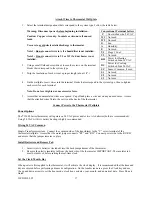
The ICM333 Head Pressure Control is factory set to maintain approximately 225 psi head pressure. Verify
the head pressure remains at 225 psi or above. See page 22 and the charging table on page 23 for
instructions on how to adjust the fan speed controller.
Never
adjust the pressure control to bring on the
condenser fan motor above 250 psi. Slowly add refrigerant until the bubbles in the sight glass disappear.
The condenser fan motor must be running to complete the charge
11.
For R-22: After the system has run for 10 minutes check the sight glass again. During normal operation
with R-22 there should be no bubbles in the sight glass. If bubbles are present, the system is low on
refrigerant. Add refrigerant to eliminate the bubbles. Charge the system to approximately 5
of sub-
cooling. To calculate sub-cooling for R-22 subtract the liquid line temperature from the saturation
temperature corresponding to the head pressure. Measure the liquid line temperature between the receiver
and filter drier with and an accurate, digital, thermocouple style thermometer.
For Nu22B or other blended refrigerants: Some bubbles may be present with a full charge of a blended
refrigerant. Charge the system to approximately 5
of sub-cooling. To determine sub-cooling for NU-22B
or other blended refrigerants, subtract the liquid line temperature from the bubble temperature
corresponding to the head pressure. Measure the liquid line temperature between the receiver and filter
drier with an accurate, digital, thermocouple style thermometer.
12.
Allow the wine room temperature to fall to 55
F.
Check the super heat at the evaporator.
Measure the
suction pressure at compressor access port. From refrigerant pressure-temperature tables, determine the
saturation temperature (for R-22) or the dew temperature for NU-22B or other blended refrigerant at the
observed suction pressure. Measure the suction line temperature at the compressor. Subtract the saturation
temperature (Dew temperature for blended refrigerants) from the measured suction line temperature. The
difference is the superheat. Refer to the temperature pressure chart on page 26 in these instructions.
The superheat should be 8
to 16
F. If the superheat is not in this range, the thermostatic expansion valve
must be adjusted. To adjust the expansion valve, remove the seal cap from the bottom of the valve. Turn
the adjustment screw clockwise to increase superheat and counterclockwise to decrease superheat.
Caution: There are 10 turns on the adjustment stem. When stop is reached while turning the
superheat adjustment stem, any further turning will damage the valve.
One complete 360
turn
changes the superheat approximately 3
-4
F. As much as 30 minutes may be required for the system to
stabilize after the adjustment is made. Replace and hand tighten the seal cap. Always replace the
evaporator face plate between TXV adjustments.
13.
Perform the final check of the refrigeration unit. The cellar temperature must be between 53
and 58
F.
Check the sight glass and gauge readings again. The super heat must be 8
-16
F (see step 12). The hot gas
line temperature must not exceed 260
F. Never exceed the maximum amp draw (RLA) for the
compressor. Adjust the TXV, and charge as necessary. All measurements should be taken with the
condenser fan motor running. All temperature readings should be taken with a digital probe style
thermometer.
14.
If the recommended system pressures and temperatures cannot be achieved, refer to the troubleshooting
chart on pages 24 and 25.
15.
Clearly mark the unit to identify the refrigerant used.


