


MAINTENANCE
CUTTER 24V 86036830 06/20/07
4-7
TO ADJUST SQUEEGEE PITCH
1.
Choose a smooth, level surface. Turn “ON” the
key switch. Lower the squeegee and drive
forward at least 2 feet (60cm.).
2.
With the squeegee down, stop the machine. Do
not allow machine to roll back.
FOR SAFETY: Before leaving or servicing the
machine; stop on level surface, turn off machine
and remove key.
3.
Determine the differences, if any, in deflection of
the squeegee blade between each end and the
middle. Proper adjustment is obtained when
deflection is equal all the way across the
squeegee blade. The bubble level should also
indicate when the squeegee is adjusted
properly. When the air bubble is in the center of
the vial, the deflection should be even across
the squeegee blade.
4.
To decrease the deflection of the squeegee
blade at the ends, tighten knob near the
squeegee center. To increase the deflection at
the ends of the squeegee assembly, loosen
knob.
5.
Check the deflection of the squeegee blades
again. Repeat steps 1 through 4 until the
deflection is equal across the entire rear
squeegee blade.
TO ADJUST AMOUNT OF REAR
SQUEEGEE DEFLECTION
1.
Choose a smooth, level surface. Lower the
squeegee and drive forward at least 2 feet
(60cm).
2.
With the squeegee down, stop the machine. Do
not allow machine to roll back.
FOR SAFETY: Before leaving or servicing
machine; stop on level surface, turn off machine
and remove key.
3.
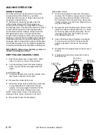
Observe the amount of squeegee deflection. It
should deflect 3/8 in. (9.5mm) across the entire
width of the squeegee.
4.
To increase the squeegee deflection, turn the 2
knobs at the squeegee ends counter-clockwise.
To decrease the deflection, turn the knobs
clockwise.
NOTE: The deflection should be consistent along
the length of the squeegee. If the deflection varies
from end to end the knobs can be adjusted
independently to correct the variation.
5.
Turn on the key switch. Raise, then lower
squeegee assembly. Drive forward at least
2 feet (60cm).
6.
Repeat steps 2 through 4 until deflection of
3/8 in. (9.5mm) is reached.
3.
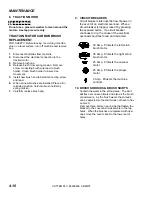
TO REPLACE AQUA-MIZER
SQUEEGEE BLADES
These squeegee blades have two wear edges. To
use the second edge:
1.
Remove deck shrouds.
2.
Remove brushes or pad drivers.
3.
Remove each of the Aqua-Mizer squeegee
systems.
4.
Remove the hardware from each system that
retains the blade.
5.
Flip the blades and replace hardware.
6.
Re-install each Aqua-Mizer system, brushes or
pad drivers and shrouds.
3/8”
PROPER DEFLECTION OF SQUEEGEE BLADE
Summary of Contents for Saber Cutter 10052360
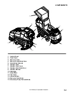
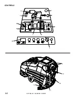
Page 12: ...CONTROLS CUTTER 24V 86036830 06 20 07 3 5 3 5 8 6 13 9 2 12 11 15 1 14 7 10 4 16 ...
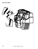
Page 34: ...CONTROL HANDLE CUTTER 24V 86036830 06 20 07 11 9 6 10 8 7 4 5 2 3 1 5 1 ...
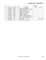
Page 36: ...COVER FRONT TANK MOUNT CUTTER 24V 86036830 06 20 07 10 9 8 7 5 1 2 6 2 3 3 5 3 ...
Page 38: ...COVER TOP TANK MOUNT CUTTER 24V 86036830 06 20 07 8 5 7 1 2 3 4 3 5 3 6 3 9 10 11 5 5 ...
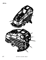
Page 40: ...DECAL CUTTER 24V 86036830 06 20 07 1 2 3 5 6 7 4 5 7 ...
Page 44: ...LIFT HANDLE CUTTER 24V 86036830 06 20 07 8 6 1 7 2 1 9 4 5 3 5 11 ...
Page 50: ...SCRUB BRUSH PAD DRIVER 3 5 1 8 9 4 6 5 7 2D 2E 2A 2C 2B CUTTER 24V 86036830 06 20 07 5 17 ...
Page 54: ...SCRUB DECK MOTORS CUTTER 24V 86036830 06 20 07 5 21 8 6 7 9 10 4 5 3 2 1 ...
Page 66: ...SOLUTION CUTTER 24V 86036830 06 20 07 7 2 3 8 4 10 9 1 5 13 12 11 10 4 6 5 33 ...
Page 72: ...VACUUM CUTTER 24V 86036830 06 20 07 4 3 2 7 8 9 6 5 1 2 1 5 39 ...
Page 74: ...WHEELS AND FRAME CUTTER 24V 86036830 06 29 11 5 41 4E 4D 6 8 7 9 10 1 2 5 4A 4C 3 4B 11 ...
Page 76: ...WIRING BATTERY CUTTER 24V 86036830 02 10 09 5 43 1 2 3 4 5 9 6 7 8 1 11 10 12 13 ...
Page 83: ...CUTTER 24V 86036830 06 20 07 5 50 THIS PAGE LEFT BLANK INTENTIONALLY ...
Page 86: ...EMERGENCY STOP OPTION CUTTER 24V 86036830 06 20 07 1 5 53 ...