background image

Installation – 

Mounting Height & Clearance

6

www.windcrestcnp.com

DUCTING

A minimum of 10” round duct must be used to 

PDLQWDLQPD[LPXPDLUÀRZHI¿FLHQF\

Always use rigid type metal ducts only. Flexible 

GXFWVFRXOGUHVWULFWDLUÀRZE\XSWR

$OVRXVHFDOFXODWLRQRQSDJHWRFRPSXWHWRWDO

available duct run when using elbows, transitions 
and caps.

ALWAYS, when possible, reduce the number or 
transitions and turns. If long duct run is required, 
increase duct size. 

If turns or transitions are required; install as far 
away from hood duct output and as far apart, 
between the two as possible.

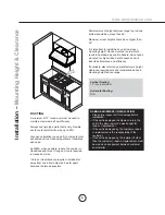
Minimum mount height between range top to hood 
bottom should be no less than 26”. 

Maximum mount height should be no higher than 
36”.

It is important to install the hood at the proper 
mounting height. Hoods mounted too low could 

UHVXOWLQKHDWGDPDJHDQG¿UHKD]DUGZKLOHKRRGV

mounted too high will be hard to reach and will 

ORVHLWVSHUIRUPDQFHDQGHI¿FLHQF\

If available, also refer range manufacturer’s height 
clearance requirements and recommended hood 
mounting height above range.

Vertical Ducting: 

10” round minimum
 

Horizontal Ducting:

N/A

DAMAGE-SHIPMENT / INSTALLATION:

‡ 3OHDVHIXOO\LQVSHFWXQLWIRUGDPDJHEHIRUH

installation.

‡ ,IWKHXQLWLVGDPDJHGLQVKLSPHQWUHWXUQWKH

unit to the store in which it was bought for 
repair or replacement.

‡ ,IWKHXQLWLVGDPDJHGE\WKHFXVWRPHUUHSDLU

or replacement is the responsibility of the 
customer.

‡ ,IWKHXQLWLVGDPDJHGE\WKHLQVWDOOHULIRWKHU

WKDQWKHFXVWRPHUUHSDLURIUHSODFHPHQWPXVW

be made by arrangement between customer 
and installer.

26” min.

36” max.

36”

Summary of Contents for UIX3622S

Page 1: ...nd Installation Guide www windcrestcnp com Model number Serial Number Date of Purchase Sales Dealer Copyright 2014 CNP Industries Inc UIX3622S UIX4822S Insert with 1200 CFM Blower READ AND SAVE THESE INSTRUCTIONS ...

Page 2: ...www windcrestcnp com ...

Page 3: ...g Options 7 6SHFL FDWLRQV 8 Electrical 9 Installing the One Piece Insert 10 Insert Preparation 11 FEATURES CONTROLS Touch Controls 12 13 RF Remote Control 14 MAINTENANCE Cleaning Installing Filters 15 Lights 16 TROUBLESHOOTING 17 FAN CURVE WIRING DIAGRAMS 18 LIST OF PARTS ACCESSORIES 19 WARRANTY 20 Table of Contents ...

Page 4: ...are and utensils appropriate for the type of and amount of food being prepared WARNING TO REDUCE THE RISK OF INJURY TO PERSONS IN THE EVENT OF A RANGE TOP FIRE OBSERVE THE FOLLOWING D 6027 5 0 6 ZLWK D FORVH WWLQJ OLG FRRNLH VKHHW RU PHWDO WUD WKHQ WXUQ RII WKH EXUQHU 5 8 72 35 9 17 8516 I WKH ÀDPHV GR QRW JR RXW LPPHGLDWHO 9 8 7 1 7 5 3 570 17 b NEVER PICK UP A FLAMING PAN You may be burned c DO ...

Page 5: ...ground circuit National Fire Protection Association Batterymarch Park Quincy Massachusetts 02269 CSA International 8501 East Pleasant Valley Road Cleveland Ohio 44131 5575 This appliance requires a 120V 60Hz electrical supply and connected to an individual properly grounded branch circuit protected by a 15 or 20 ampere circuit breaker or time delay fuse Wiring must be 2 wire with ground Please als...

Page 6: ...G IRU 8 6 XDO LQWHUQDO EORZHU SUH LQVWDOOHG 1 10 round duct collar 5 UHPRWH FRQWURO ZLWK EDWWHU KROGHU 1 Hardware package HARDWARE PACKAGE CONTENTS PARTS NOT SUPPLIED Ducting conduit and all installation tools Cable connector if required by local codes Light Bulb Removal Suction Cup 1 M4 x 6mm 4 Wire Caps 3 8 x 1 2 12 RF Remote Control 1 Remote Holder 1 ...

Page 7: ... Ft 6 Round straight 1 Ft x Ft Subtotal column 1 Duct pieces T otal Equivalent number length x used 6 Round wall cap with damper 30 Ft x Ft Round wall cap with damper 30 Ft x Ft 7 10 Round 900 elbow 15 Ft x Ft 7 10 7 10 Round 450 elbow 9 Ft x Ft Ft Ft Ft 6 Round roof cap 30 Ft x Ft 7 10 Round roof cap 30 Ft x Ft Subtotal column 2 Subtotal column 1 Total ductwork 6 roundto 3 1 4 x 10 rect transitio...

Page 8: ...e no higher than 36 It is important to install the hood at the proper mounting height Hoods mounted too low could UHVXOW LQ KHDW GDPDJH DQG UH KD DUG ZKLOH KRRGV mounted too high will be hard to reach and will ORVH LWV SHUIRUPDQFH DQG HI FLHQF If available also refer range manufacturer s height clearance requirements and recommended hood mounting height above range Vertical Ducting 10 round minimu...

Page 9: ...st must be ducted to the outside Use single wall rigid metal ductwork only DVWHQ DOO FRQQHFWLRQV ZLWK VKHHW PHWDO VFUHZV DQG WDSH DOO MRLQWV ZLWK FHUWL HG 6LOYHU 7DSH RU XFW 7DSH Some Ducting Options Installation Ducting Options side wall cap w gravity damper side wall cap w gravity damper Soffit or crawl space Roof Pitch w Flashing Cap ...

Page 10: ...windcrestcnp com Installation 6SHFL FDWLRQV Top View 3 4 View Back View 34 3 8 46 3 8 3 12 28 3 8 40 3 8 22 1 2 5 5 8 34 17 1 4 46 23 1 4 C L Ø 10 34 12 46 18 2 elec k o C L 10 3 8 34 12 46 18 4 3 8 elec k o ...

Page 11: ...ling local codes and ordinances Electrical Supply This appliance requires a 120V 60Hz electrical supply and connected to an individual properly grounded branch circuit protected by a 15 or 20 ampere circuit breaker or time delay fuse Wiring must be 2 wire w ground Please also refer Electrical Diagram labeled on product Cable Lock FDEOH ORFNLQJ FRQQHFWRU QRW VXSSOLHG PLJKW DOVR EH UHTXLUHG E ORFDO ...

Page 12: ... insert to is capable of holding the weight of UIX3622S or UIX4822S Failure to do so may cause personal injury or damage to cooking surface or counter 5 Finalize installation of electrical and duct work Seal duct work with FHUWL HG DOXPLQXP GXFW WDSH 3RZHU RQ LQVHUW FKHFN IRU OHDNV DURXQG duct tape and verify proper operation NOTE If access to top of insert is not available after installation elec...

Page 13: ... panels by UHPRYLQJ VFUHZV IURP EHKLQG HDFK SDQHO Installation Insert Preparation 1 2 1 1 2 Locking Tabs Bottom Panel Screws 2 2 1 4 Remove bottom panel by 1 5HPRYLQJ screws from left and right sides of bottom panel 2 Pulling bottom panel toward front of insert to release from locking tabs 6 Hood preperation is complete Refer to page 10 step 4 to complete installation 5 Secure 10 round ducting col...

Page 14: ...ay indicates levels selected 3 Delay Off This feature is used for programmed shut down of blower 5 minutes after the function is activated Press once a dot flashes in the lower right side of display indicating the function is on The blower will completely shut down after 5 minutes 4 Lights On Dim Off Switch lights on by pressing once press a second time to dim and again to shut off lights 5 Displa...

Page 15: ...s are cleaned and re installed With hood off press and hold for approximately 5 seconds until on display disappears The filter clean reminder function is now reset and a new 30 hours elapse cycle is initiated F Clean Filters display F flashes F hold 5 sec display from F to To Reset F A hold 3 sec display from A to To Disable hold 3 sec To Enable F F display A flashes A A 1 A 1 Refresh Air Indicato...

Page 16: ...ssing the blowers will power on at the last speed setting Press again and the entire hood will power off including lights Delay Off Lights On Dim Off Switch lights On by pressing once again to dim and again to switch Off Blower On Speed Selection 1 1 2 3 4 Blower On Power Off 2 5 Min Delay Off 3 Lights On Dim Off 4 By pressing the blower and lights will enter Delay Off mode A dot will appear in th...

Page 17: ...W VRDS ZDWHU U OWHUV DQG UH LQVWDOO EHIRUH using hood QVWDOOLQJ WKH DIÀH OWHUV 3ODFH OWHU LQWR WRS JURRYH RI WKH LQVHUW DV VKRZQ DQG pull towards front of insert using handles 3LYRW EDFN RI OWHU XSZDUGV VR LW LV DQJOHG LQ WKH LQVHUW 3XVK OWHU LQWR FKDQQHO RQ EDFN RI LQVHUW WR ORFN LQWR SODFH 5HSODFLQJ WKH DIÀH LOWHUV Hood Model Part No Qty to Order 8 6 8 6 6 ODUJH 8 6 6 VPDOO 8 6 6 VPDOO Cleaning ...

Page 18: ...t Remove by turning bulb counter clockwise Note Bulb does not unscrew it turns 60 degrees stops and falls out I EXOEV DUH GLI FXOW WR WXUQ GXH WR SURORQJHG XVH UPO DWWDFK WKH JODVV VXFWLRQ FXS SURYLGHG WR WKH EXOE RU use a rubber latex glove and turn counter clockwise 5HSODFHPHQW EXOEV DUH DYDLODEOH DW VSHFLDOW OLJKWLQJ VWRUHV 3XUFKDVH W SH 05 8 KDORJHQ For Wind Crest part numbers please turn to p...

Page 19: ...the hood 3 Damaged blower wheel 3 Change the blower The unit is whistling 7KH OWHU LV QRW LQ WKH FRUUHFW SRVLWLRQ GMXVW WKH OWHUV XQWLO WKH ZKLOVWOLQJ VWRSV 2 The duct pipe connections are not sealed or connected properly 2 Check the duct pipe connections to be sure all connections are sealed properly The blower is working but the lights are not 1 Defective halogen bulb 1 Change the halogen bulb 2...

Page 20: ... 0 40 0 50 0 60 0 70 0 80 0 50 100 150 200 250 300 350 400 450 500 550 600 650 700 750 800 850 900 950 1000 1050 1100 1150 1200 1250 1300 Flow rate CFM Model UIX3622S w p bu g y r br b THERMALLY PROTECTED Fan 633W Lamp Max 35Wx2 Total Max 703W 7A Voltage 120V 60Hz Power consumption THERMALLY PROTECTED Fan 633W Lamp Max 35Wx4 Total Max 773W 7A Voltage 120V 60Hz Power consumption w p bu g y r br b M...

Page 21: ... 8 HDFK 6 8 6 8 6 DIÀH LOWHU DUJH HDFK 6 8 6 8 6 DIÀH LOWHU 6PDOO HDFK 6 RF Remote Control S12313 00 Light Bulb Removal Suction Cup S11557 00 To order parts visit us online at www windcrestcnp com or call us at 1 877 387 6721 List of Parts Accessories ...

Page 22: ...ed agency or use of unauthorized parts 2 Service visits to teach you how to use the appliance 3 Correct installation related problems you are responsible for providing electrical wiring and other connection items 4 Reset circuit breakers or replace fuses 5 Damage caused by abuse accident alteration misuse and local code violations 6 Failure due to other than normal house use You may also write to ...

Reviews: