21
60706-229/G
DSE 3110 ENGINE CONTROL
PROTECTIONS
When an alarm is present, the Common alarm LED (if
configured) will illuminate. The LCD display will show an icon
to indicate the failure.
WARNINGS
Warnings are non-critical alarm conditions and do not affect
the operation of the generator system; they serve to draw the
operator’s attention to an undesirable condition. Warning
alarms are self-resetting when the fault condition is removed.
The icon will appear steady in the display.
SHUTDOWNS
Shutdowns are critical alarm conditions that stop the
engine and draw the operator’s attention to an undesirable
condition. Shutdown alarms are latching. The fault must be
removed and the Stop/Reset button pressed to reset the
module. The icon will appear flashing in the display.
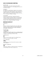
MODULE DISPLAY
TIMER ICON
When the module is controlling the engine (starting and
stopping), an animated timer icon will be displayed in the
icon area to indicate that a timer is active. For example,
cranking time, crank test, etc.
STOPPED ICON
When there are no alarms present, an icon will be displayed
to indicate the engine is stopped and what mode the unit is
in Stop mode, Auto mode, or Manual mode.
RUNNING ICON
When there are no alarms present, an animated icon is
displayed to indicate the engine is running.
USB CONNECTION
When a USB connection is made to the module, the USB
icon is displayed.
MEMORY CORRUPTION
If either the config file or engine file becomes corrupted, the
unit will display the memory corruption icon.
Summary of Contents for PSS20B2W/A
Page 19: ...19 60706 229 G...
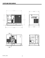
Page 24: ...24 60706 229 G OUTLINE DRAWING...
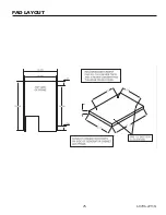
Page 25: ...25 60706 229 G PAD LAYOUT 60706 229 23 12270 01 60706 229 ET A ENGINE GENERATOR SET PAD LAYOUT...
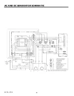
Page 26: ...26 60706 229 G AC AND DC GENERATOR SCHEMATIC...
Page 27: ...27 60706 229 G AC WIRING SCHEMATIC PSS20 3 A PSS20 17 A PSS20 18 A PSS20 4 A...

