background image

5

OPM-125/D

is not able to supply enough power to bring the electric 

motor up to operating speed. The generator responds with 

high initial starting current, but the engine speed drops 

sharply. The overload may stall the engine. If allowed to 

operate at very low speeds, the electric motor starting 

winding will burn out in a short time. The generator 

winding may also be damaged.

CAUTION: EQUIPMENT DAMAGE

Running the generator set under these conditions may 

result in damage to the generator stator as well as the 

motor winding.

The heavy surge of current required for starting motors 

is required for only an instant. The generator will not be 

damaged if it can bring the motor up to speed in a few 

seconds of time. If difficulty is experienced in starting 

motors, turn all other electrical loads off and if possible 

reduce the load on the electric motor.

Motor starting capacity -  2HP code ‘G’ capacitor start 

engine.

Trying to start a larger motor or higher code motor, i.e. ‘J’ 

or ‘K’, may result in damage to both the generator and the 

electric motor, especially 120 Volt motors.

LOAD TYPES

This generator is designed and rated for general 

commercial use. The running watts rating assumes a 

variable load. If your application has a fixed load that does 

not vary, an additional derate of 20% from the running 

watts is recommended to ensure the longest useful life of 

the engine and generator end. 

UNIT CAPABILITIES

GENERATOR CONNECTIONS

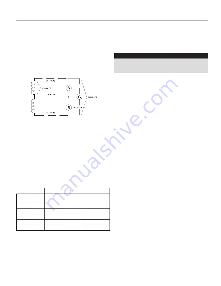
EC6010: 120 Volt and 240 Volt receptacles are provided 

for connection to various loads. The following diagram 

represents this 5,160 watt (rated output) generator. A & 

B represent the 120 volt output legs of this generator. Up 

to 2,580 watts at 120 volts (43 Amps) can be drawn from 

the receptacles attached to either A or B output legs. This 

generator is capable of producing 21.5 Amps of 240 volt 

current at C. Check the appliance or tool nameplates for the 

current and voltage to insure compatibility. Remember that 

power taken from C reduces the power available equally at 

both A and B and vice versa.

STARTING ELECTRIC MOTORS

Electric motors require much more current (amps) to start 

them than to run them. Some motors, particularly low cost 

split-phase motors, are very hard  to start and require 5 to 7 

times as much starting current as running current. Capacitor 

motors are easier to start and usually require 2 to 4 times 

as much starting current as running current. Repulsion 

Induction motors are the easiest to start and require only 1 

1/2 to 2 1/2 times as much starting as running current.

Most fractional horsepower motors take about the same 

amount of current to run them whether they are Repulsion 

Induction (RI), Capacitor (Cap), or Split-Phase (SP) type. The 

following chart shows the approximate current required to 

start and run various types and sizes of 120 Volt 60 cycle 

electric motors under average load conditions.  

STARTING AMPS

HP

Running 

Amps

Split Phase 

Motor

Capacitor 

Motor

Repulsion 

Induction Motor

1/6

3.2

16 to 22

6 to 13

5 to 8

1/4

4.5

22 to 32

9 to 18

7 to 12

1/3

5.2

26 to 35

10 to 21

8 to 17

1/2

7.2

Not Made

14 to 29

11 to 18

1

13

Not Made

26 to 52

20 to 33

The figures given in the previous chart are for an 

average load such as a blower or fan. If the electric 

motor is connected to a hard starting load such as an air 

compressor, it will require more starting current. If it is 

connected to a light load, or no load such as a power saw, 

it will require less starting current. The exact requirement 

will also vary with the brand or design of the motor.

Self-exciting generators respond to severe overloading 

differently than utility power. When overloaded, the engine 

Summary of Contents for EC6010DR/T

Page 1: ...ould ever need to contact us on this unit it will help us to respond to your needs faster MODEL __________________________________________________ SERIAL NUMBER _______________________________________...

Page 2: ...CLEANING TROUBLESHOOTING 18 CONTROL PANEL WIRING DIAGRAM 19 CA EVAP EMISSION CONTROL 20 LIMITED WARRANTY 20 SAVE THESE INSTRUCTIONS This manual contains important instructions that should be followed...

Page 3: ...sent a hazard of possible explosion and or fire A Do not refuel when the engine is running or hot B Keep fuel containers out of reach of children C Do not smoke or use open flame near the generator se...

Page 4: ...store the unit outside during inclement weather without adequate protection from the elements Failure to do so will damage the unit DO NOT remove from the cradle assembly Removal of the generator fro...

Page 5: ...ceptacles attached to either A or B output legs This generator is capable of producing 21 5 Amps of 240 volt current at C Check the appliance or tool nameplates for the current and voltage to insure c...

Page 6: ...to refuse the shipment and let WINCO take care of the freight claim If you sign for the unit the transfer of the ownership requires that you file the freight claim 2 Before proceeding with the prepara...

Page 7: ...e hydrogen gas when charging Keep sparks flames and burning cigarettes away from the battery Ventilate the area when charging or using the battery in an enclosed space Lead acid batteries contain sulf...

Page 8: ...battery with water use only distilled water Tap water will shorten the service life of the battery Never fill the battery above the fill line Overfilling above the upper level line may cause the elec...

Page 9: ...reen wire connects to the skid base There may already be a ground wire screwed down add the green wire and re secure the screw The black longer wire will connect to the front of the engine Attach blac...

Page 10: ...Preferred fuel installations use 1 4 hose that run straight to the engine with no drops or twists from an adequately sized fuel tank Connect a 1 4 fuel hose to the hose fitting located on the fuel pum...

Page 11: ...nd dry area 0 INITIAL START UP The throttle control on these generators is preset and locked to operate at 3600 RPM nominal with no load speed set at 3690 RPM Only a trained service technician should...

Page 12: ...system When connecting it to a building a transfer switch specifically designed for GFCI and bonded neutral generators is required CONNECTING THE LOADS The engine generator covered in this manual was...

Page 13: ...set is connected to an existing distribution system a fully isolated manual transfer switch must be installed The transfer switch prevents damage to the generator and the other circuit components if...

Page 14: ...5 25 50 50 75 75 100 YOURGEN The WINCO YourGen meter allows you to see useful information about your generator from the front panel by displaying RPMs Voltage frequency load hours and maintenance remi...

Page 15: ...This generator is capable of producing 21 5 Amps of 240 volt current at C Check the appliance or tool nameplates for the current and voltage to insure compatibility Remember that power taken from C r...

Page 16: ...with the air filter removed A Remove the cover ENGINE CARE MAINTENANCE SCHEDULE Daily or Every 10 hrs Every 250 hrs Every 500 hrs Check Oil Check oil filter Check dry air cleaner Fuel tank cleaning C...

Page 17: ...is excessively dirty replace with a new filter You can use pressurized air not to exceed 30 psi to clean the filter Always blow the compressed air from inside to the outside F Clean the dirt from the...

Page 18: ...generator components 1 Keep the air inlet screen on both the engine and generator free of any dirt or debris to ensure proper cooling At least yearly remove the blower housing on the engine and clean...

Page 19: ...19 OPM 125 D CONTROL PANEL WIRING DIAGRAM G1 G1 G1 G2 G N N G G G2 G2...

Page 20: ...uest THERE ARE NO EXPRESS WARRANTIES OTHER THAN THOSE DESCRIBED HEREIN THERE ARE NO OTHER WARRANTIES EXPRESSED OR IMPLIED OR OTHERWISE CREATED INCLUDING BUT NOT LIMITED TO WARRANTIES OF MERCHANTABILIT...

Reviews: