background image

Installation and operating instructions Wilo-DrainLift S 39

MAINTENANCE AND REPAIR English

• Lifting equipment in perfect technical condition 

and officially approved load‑bearing equipment 
must be used for lifting and lowering the lifting 
unit.

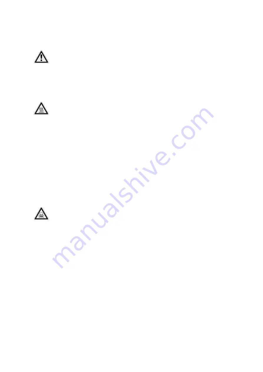
RISK of death due to malfunction! 

Lifting gear and equipment must be in 

perfect technical condition. Work may only 

commence if the lifting equipment has been 

checked and found to be in perfect working 

order. If it is not inspected, fatal injuries may 

result.

7.1.  Switching off the unit

BEWARE of burns! 

The motor housing can reach temperatures 

well in excess of 40 °C. There is a risk of 

burns! After switching off, first let the motor 

cool down to ambient temperature.

1.  Close the gate valve in the inlet pipe.
2.  Drain the collection reservoir. To do this, switch 

the unit on in manual operation using the manual 
button for no more than 20 seconds.

3.  Switch the lifting unit to standby mode via the 

switchgear.

4.  Pull the plug out of the socket.
5.  Secure the unit against being unexpectedly 

switched back on!

6.  Close the gate valve in the pressure pipe.
7.  Now it is possible to start the work of removal, 

maintenance and putting into storage.

7.2.  Removal

DANGER due to toxic substances! 

During removal, there is potential for contact 

with fluids that represent a health hazard. The 

following points must be observed without 

fail:

•  Wear appropriate full-body protection as well 

as protective goggles and mouth protection.

•  Immediately wipe up drips.
•  All components must be cleaned and disin-

fected!

•  Channel the flushing water into the sewer 

system at suitable points!

•  The protective clothing and cleaning cloths 

must be disposed in accordance with waste 

code TA 524 02 and EC Directive 91/689/EEC 

or with local directives.

1.  Switch off the unit as described in the “Switching 

off the unit” section.

2.  Close all gate valves.
3.  Open the non-return valve using the ventilation 

device in order to drain the pressure pipe into the 
reservoir.

4.  Disconnect the connection between the inlet 

pipe and the inlet seal, and pull the inlet pipe out 
of the seal.

5.  Disconnect the connection between the non-re-

turn valve and the pressure port.

6.  Disconnect the connection between the ventila-

tion pipe and the ventilation connection, and pull 
the pipe up off the connecting piece.

7.  Also remove the DN 40 inlets if there are any.
8.  Then disconnect the diaphragm hand pump from 

the lifting unit if it is installed.

9.  Once all connections have been disconnected, 

release the anchoring points of the lifting unit in 
the floor

10.  Now the lifting unit can be pulled carefully out of 

the pipework.

11.  Flush through the lifting unit with clean water and 

disinfect it

12.  Firmly close all connecting pipes, clean and disin-

fect them.

13.  Clean the operating space and disinfect it if 

necessary.

7.3.  Return delivery/storage

Lifting units that are sent back to the factory 
must be cleaned to remove impurities and, if they 
have been used with fluids that are harmful to 
health, they must also be decontaminated.
For shipping, the parts must be packed in tear-
proof plastic bags of sufficient size in such a 
manner that they are tightly sealed and leak-
proof. Furthermore, the packaging must protect 
the lifting unit from damage during transporta-
tion. If you have any questions, please contact 
the manufacturer!

For return delivery and storage please also refer 

to the “Transport and storage” section!

7.4.  Disposal

7.4.1.  Protective clothing

The protective clothing and cleaning cloths 
must be disposed in accordance with waste code 
TA 524 02 and EC Directive 91/689/EEC or with 
local directives.

7.4.2.  Product

Proper disposal of this product avoids damage to 
the environment and risks to personal health.

• Use the services of public or private waste dis-

posal companies, or consult them for the disposal 
of the product or parts thereof.

• For more information on proper disposal, please 

contact your local council or waste disposal office 
or the supplier from whom you obtained the 
product.

8.  Maintenance and repair

For reasons of safety, and thus to guarantee cor-
rect function of the lifting unit, it must always be 
maintained by Wilo customer service. 
The maintenance intervals for lifting units are 
determined by EN 12056‑4:

• ¼ year in the case of commercial companies
• ½ year for units in multi-family houses
• 1 year for units in single-family houses

Summary of Contents for DrainLift S

Page 1: ...uctions fr Notice de montage et de mise en service es Instrucciones de instalaci n y funcionamiento it Istruzioni di montaggio uso e manutenzione pt Manual de Instala o e funcionamento nl Inbouw en be...

Page 2: ...Fig 3 Fig 2 Fig 5 Fig 1 1 3 3 2 4 4 5 5 6 9 9 6 6 6 7 7 8 1 1 1 2 2 40 60 mm 1 2 3 4 5 7 6 10 20 mm 1 1 1 1 1 3 2 3 3 4 4 4 5 5 1 2 3 4...

Page 3: ...Fig 7 Fig 6 Fig 8 Fig 4 45 290 45 60 45 290 45 60 45 45 45 80 min 180 mm 1 50 1 2 3 4 5 5 1 15 mm 1 2 1 3 2...

Page 4: ...0Hz 1 brown yellow green white grey blue brown black 2 3 4 5 L1 L2 L3 PE 3 400V 50 60Hz L1 L L2 N PE 1 230V 50 60Hz 1 230V 50Hz 30 15 0 Seconds ON 100 K DIP 1 2 3 4 5 6 7 PE SSM 1 2 3 7 8 9 4 5 6 GL W...

Page 5: ......

Page 6: ...key 30 3 7 Scope of delivery 30 3 8 Accessories optionally available 30 4 Transportation and storage 31 4 1 Delivery 31 4 2 Transport 31 4 3 Storage 31 4 4 Return delivery 32 5 Installation 32 5 1 Gen...

Page 7: ...he lifting unit indicated on the title page 1 5 Warranty In general the specifications in the current gen eral terms and conditions apply for the warranty You can find these here www wilo com legal An...

Page 8: ...erator must report any faults or irregulari ties that occur to a line manager immediately The end user must shut down the equipment im mediately if defects occur that represent a safety risk These inc...

Page 9: ...e for ensuring that regulations are observed 2 6 Fluids The lifting unit chiefly collects and pumps waste water containing faeces As a result changing to a different fluid is not possible Use in drink...

Page 10: ...is ready for connection as a single pump system Fig 1 Description 1 Collection reservoir 6 Inlet DN 40 2 Inspection opening 7 Ventilation connection 3 Level control 8 Pressure connection 4 Motor 9 Fa...

Page 11: ...id grain size 40 mm Motor data Mains connection U f See rating plate Power consumption P1 See rating plate Rated power P2 See rating plate Rated current IN See rating plate Speed n See rating plate Ac...

Page 12: ...tions and deposits building up in the collection reservoir on the level control and the pump hydraulics DANGER due to toxic substances Flushing through the lifting unit contami nates the flushing wate...

Page 13: ...tallation types Stationary dry well installation in buildings and pump chambers 5 3 Installation DANGER due to overpressure Exceeding the application limits can result in excessive pressure in the col...

Page 14: ...the lifting unit These must be attached to the reservoir Lifting gear must be technically approved Also refer to all regulations rules and laws for working with heavy and suspended loads Wear appropri...

Page 15: ...oo small the discharge pipe or the flange connector must be shortened If the distance is too large the hose section can not be properly secured 6 Align the flexible connecting hose to the centre and u...

Page 16: ...ing unit The min connection height is 180 mm NOTE When using the DN 40 connection on the lon gitudinal side it is always possible that drainage problems will arise for physical reasons The inlet must...

Page 17: ...sitions of the indi vidual DIP switches Read the installation and operating instructions for the fitted switchgear 5 4 4 Connecting an external alarm signal The switchgear is fitted with a buzzer in t...

Page 18: ...rating conditions The lifting unit is only allowed to be operated under the following conditions Max intake h 600 l Max suction head 5 m Max permitted pressure in pressure pipe 1 5 bar Max fluid tempe...

Page 19: ...gency operation DANGER due to toxic substances During emergency operation there is poten tial for contact with fluids that represent a health hazard The following points must be observed without fail...

Page 20: ...e seal 5 Disconnect the connection between the non re turn valve and the pressure port 6 Disconnect the connection between the ventila tion pipe and the ventilation connection and pull the pipe up off...

Page 21: ...Have the mains connection checked elec trician 5 Running on two phases Renew defective fuse electrician Check the electrical connection electrician 6 Motor does not start because there is no voltage C...

Page 22: ......

Page 23: ...Pioneering for You WILO SE Nortkirchenstra e 100 44263 Dortmund Germany T 49 0 231 4102 0 F 49 0 231 4102 7363 wilo wilo com www wilo com...

Reviews: