


en
Decommissioning/dismantling
24
WILO SE 2017-06
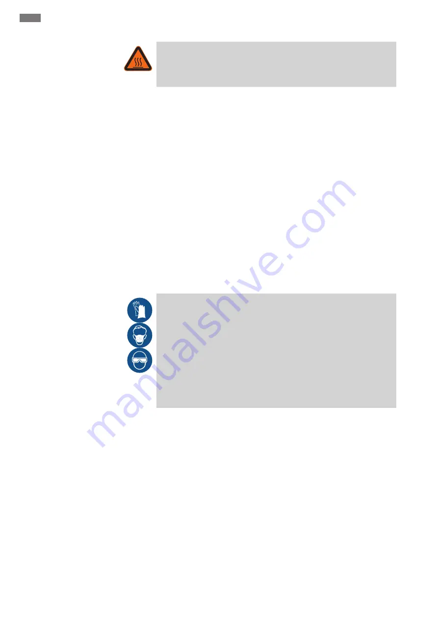
WARNING
Risk of burns from hot surfaces!
Motor housing can become hot during operation. It may cause burns. Allow the mo-
tor to cool down at ambient temperature after switching it off!
‡
Lifting unit switched off.
‡
Protective equipment put on.
‡
All gate valves (inlet and pressure pipe) closed.
1. To drain the pressure pipe into the reservoir, open the non-return valve using the
ventilation device.
2. Loosen the connection between the inlet pipes and pull the inlet pipe out of the
inlet seal.
3. Disconnect the connection between the non-return valve and the pressure port.
4. Disconnect the connection between the ventilation pipe and the ventilation con-
nection, and pull the pipe up off the connecting piece.
5. If present: Loosen and remove the DN 40 inlets (additional inlet or diaphragm hand
pump).
DANGER! Health risk due to contact with sewage! Via the lower DN 40 connec-
tion, the remaining sewage can flow out of the collection reservoir. The sewage
must be collected in suitable containers and fed into the sewer system.
6. Release the anchoring point.
7. Pull the lifting unit carefully out of the pipework.
▶ Lifting unit is dismantled. Clean and disinfect the lifting unit and operating space.
9.4
Clean and disinfect
DANGER
Danger due to fluids hazardous to health!
If the lifting unit is used to pump fluids that are hazardous to health, decontaminate
the lifting unit before carrying out any other work! Wear the following protective
equipment while performing cleaning tasks:
• Closed safety goggles
• Breathing mask
• Protective gloves
⇒ The equipment listed here is the minimum requirement, observe the spe-
cifications of the work regulations! The operator must make sure that the
personnel have received and read the work regulations!
‡
Lifting unit is dismantled.
‡
Switchgear packaged watertight.
‡
The rinsing water is disposed of in the sewage in accordance with the locally ap-
plicable regulations.
‡
A disinfectant in accordance with work regulations is available for contaminated
lifting units.
NOTICE! Strictly observe the manufacturer’s specifications concerning use!
1. Spray the lifting unit with clean water from top to bottom.
2. Open the collection reservoir and spray the collection reservoir and all connection
ports on the inside.
3. Flush all dirt residue onto the floor of the channel.
4. Allow the lifting unit to dry out.


