9
Wilo-ICL - Installation and Operation Manual
8.
8.1
Fill and Ventilate
Ventilate
6.2.5
Caution: Damage due to overheating!
For insulated piping systems, only the pump volute
may be insulated, not the lantern and the motor. These
could be damaged by heat build-up.
9.
10.
10.1
10.2
Maintenance and Repair
Cleaning
Clean the exterior of the pump using only a
lightly damp-ened cloth without detergents.
Checks
Under normal operating conditions, the pump
does not require regular maintenance work. The
following points, however, must be checked at
regular intervals.
Warning: Danger due to hot liquid under pressure!
Extreme caution must be used when venting systems
that have elevated temperatures and/or dangerous
fluids. Maintain sufficient distance from the air vent
opening. Wear suitable clothing including protective
glasses/facial protection and gloves.
Caution: Damage due to cavitation!
Failing to maintain minimum pressure on the suction
side can to lead to cavitation accompanied by noise.
This can damage the pump. This minimum inlet
pressure depends on the operating conditions and
the duty point of the pump and must be calculated
accordingly. Please contact WILO or your WILO
distributor if this information is required.
8.2
8.3
1.
2.
3.
4.
5.
6.
7.
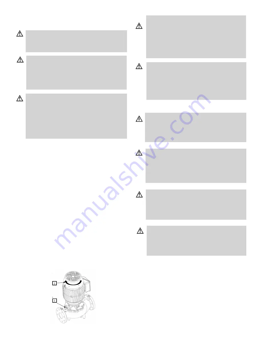
Open air vent valve (1) 1/2 turn, do not remove.
Completely open suction side and discharge
side isolation valves.
Wait until the liquid has exited the ventilation
opening and until bubbles no longer form.
Tightly close the ventilation opening.
Avoid Cavitation
Ensure that the minimum pressure stipulated
in the product catalog is present on the suction
side.
Check Direction of Rotation
Check the motor’s direction of rotation by
briefly turning it on. The direction of rotation is
correct if the fan or other visibly rotating parts
of the pump are rotating in the direction of the
arrow (2).
* On three phase only, if the direction of
rotation is incorrect, have an electrician correct
it by swapping two phases.
Turn on the pump for test operation and
observe whether it is pumping correctly. If
necessary, ventilate again until a sufficient
pumping result is achieved.
Operation
Warning: Risk of burning or freezing if the pump is
touched!
Depending on the operating conditions of the pump
or installation (liquid temperature), the entire pump
can become very hot or very cold. Keep your distance
during pump operation!
Caution: Damage due to overheating!
The pump may not be operated longer than 1 minute
without flow. An accumulation of energy creates
heat that can damage the pump shaft, impeller and
mechanical seal. A minimum flow rate of approx. 10%
of maximum flow rate must always be guaranteed.
Danger: Life threatening due to electrical shock!
Touching live components can be fatal. Only qualified
electricians may work on the electrical system. Prior to
any maintenance work, disconnect the pump from the
power supply and secure against reconnection.
Warning: Damage due to incorrectly tightened
screws!
Overtightened screws can break off. Subsequently,
separate parts and fragments may chip off and / or the
hot liquid may spray. Observe screw tightening torque
specifications L Page 11
Warning: Danger due to hot liquid under pressure!
During dismantling of motor or pump, hot liquids may
escape under high pressure. Allow the pump to cool
down first. Close isolation valve prior to dismantling
pump.
Caution: Damage due to incorrectly performed
maintenance!
Incorrectly performed maintenance work can damage
the pump. The maintenance work described below
may therefore only be performed by trained personel.


